Page
99
10 INSTALLATION REQUIREMENTS
The boiler installation must be in compliance with relevant standards and Building Regulations.
See Section 4.2 of this manual.
10.1 General Requirements
10.1.1 Hearth
The boiler has a hearth temperature of between 50°C and 85°C and should be stood on a rigid,
non-porous, non-combustible base, which is not softened by warmth, to comply with the
Building Regulations.
10.1.2 Service Access
24” (600mm) Clearance should be provided above and in front of the boiler to allow for routine
servicing. Pumped, System and Combination Boiler models may require access to the top. This
is of particular relevance to appliances located beneath work surfaces. Such work surfaces
should be easily removable for service access.
10.1.3 Heating System
The heating system should be installed to current HVAC codes of practice. Before installing the
boiler the new or existing system must be thoroughly flushed to clear all sludge or other foreign
matter such as solder, steel wool and copper filings. The system must be cleansed, neutralised
and protected from corrosion in accordance with BS12828, BS12831, BS14336 and BS7593
using suitable cleansing agent(s) and inhibitor(s) and carried out in accordance with the
cleanser / inhibitor manufacturers’ instructions. The system must be dosed to the concentrations
specified by the inhibitor manufacturer (refer to the Technical Data section of this manual for the
volume of the boiler when calculating the total system volume). Inhibitor concentrations must be
monitored and maintained on an ongoing basis. Failure of components such as, but not limited
to heat exchangers, condensing units, pumps, auto air vents and pressure relief valves, etc. due
to corrosion products in the system will not be covered by warranty.
10.1.4 Air Vents
The plastic plugs of the auto air vent(s) factory-fitted to the boiler must be loosened when filling
the system in order to bleed the air from the boiler. Air must also be vented from combination
boilers using the manual air vents located in the heat store tank and boiler flow pipe assembly.
The plugs should be tightened again once filling is complete. In addition to any factory fitted air
vents it is recommended that another air vent is fitted at the highest point in the system. Where
the flow pipework drops down from the boiler the installer must ensure that an automatic air
vent is fitted to the top of the pipework to prevent air being trapped in the boiler.
On B-Series models, the boiler
MUST
be fitted with an automatic air vent as shown in Section
4.5.1. If an air vent is not fitted, air will accumulate in the secondary heat exchanger and cause
the boiler to malfunction. Failure to fit an air vent will invalidate ALL warranties.
10.1.5 Drain Cock
For all appliances not factory-fitted with drain cocks, one should be fitted to the boiler drain boss
located to the left hand side of the burner. Drain cocks should also be fitted to the lowest points
in the system to allow the system to be completely drained.
2500 Overs
WAR139220 Agentis Boiler Manual
Sig
8 Back
Содержание Agentis Series
Страница 2: ......
Страница 30: ...Page 29 4 5 Components 4 5 1 B Series Boilerhouse Casing Key Components...
Страница 31: ...Page 30 4 5 2 I Series Internal Casing 21 26 33 Models 44 Models...
Страница 32: ...Page 31 4 5 3 I Series Internal Key Components 21 26 33 Models 44 Models...
Страница 33: ...Page 32 4 5 4 I Series Internal Pump Group 21 26 33 Models 44 Models...
Страница 34: ...Page 33 4 5 5 I Series Internal System Components SK3 4 5 6 I Series Internal Combination Boiler Key Components...
Страница 35: ...Page 34 4 5 7 E Series External Casing 21 26 33 Models 44 Models...
Страница 36: ...Page 35 4 5 8 E Series External Key Components 21 26 33 Models 44 Models...
Страница 37: ...Page 36 4 5 9 E Series External Pump Group 21 26 33 Models 44 Models...
Страница 39: ...Page 38 4 5 12 Combination Boiler Pipe Layout...
Страница 41: ...Page 40 5 1 2 I Series Internal I21 I26 I33 5 1 3 I Series Internal I44...
Страница 42: ...Page 41 5 1 4 I Series Internal Combination Boilers I21C I26C I33C 5 1 5 E Series External E21 E26 E33...
Страница 43: ...Page 42 5 1 6 E Series External Base Tray E21 E26 E33 5 1 7 E Series External E44...
Страница 44: ...Page 43 5 1 8 E Series External E44 Base Tray 5 1 9 E Series External Combination Boilers E21C E26C E33C...
Страница 45: ...Page 44 5 1 10 E Series External Combination Boiler Base Tray E21C E26C E33C...
Страница 60: ...Page 59 6 3 2 Wiring Diagram Fuses The appliance must have a permanent live supply connected to operate...
Страница 61: ...Page 60 6 3 3 External 230V Two Channel Programmer Room Thermostat Optional Outdoor sensor...
Страница 62: ...Page 61 6 3 4 Internal Two Channel Programmer and Room Thermostat Optional Outdoor Sensor...
Страница 73: ...Page 72 6 6 9 Honeywell Y Plan Independent CH DHW Fully Pumped Only 2 CHANNEL TIMECLOCK...
Страница 74: ...Page 73 6 6 10 Honeywell S Plan Independent CH DHW Fully Pumped Only 2 CHANNEL TIMECLOCK...
Страница 93: ...Page 92 Kabin Pak External Plume Management Kit KPMK The kit comprises...
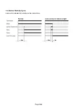
Страница 107: ...Page 106 11 4 Burner Start Up Cycle Lock out is indicated by a lamp on the control box...
Страница 122: ...Page 121 14 SPARES 14 1 RDB 2 2 BX Spares...
Страница 124: ...Page 123 14 2 RDB 3 2 BX Spares...
Страница 134: ...Page 133 Intentionally left blank...
Страница 135: ......


