Page
9
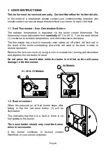
1.3 System Pressure – System & Combination Boilers
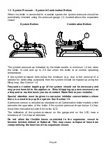
When the boiler is connected to a sealed system the system pressure should be
periodically checked using the pressure gauge (1), located above the expansion
vessel.
System Boilers
Combination Boilers
The system pressure as indicated by the black needle, is minimum 1.0 bar when
the boiler is cold and up to 2.5 bar when the boiler is at normal operating
temperature.
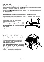
If the system pressure falls below the minimum (e.g. due to the removal of a
radiator for decorating purposes) then the system should be topped up using the
filling loop. See Section 1.4.
Frequent or routine topping up of the system should not be necessary and
may prove harmful to the appliance. Should topping up prove necessary on
a frequent or routine basis you must contact Warmflow or your installer.
Special attention must be given to corrosion inhibitor concentrations where
there is a need to top up the system. See Section 1.5.
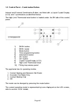
A pressure sensor is included as standard on all Combination boiler models which
prevents the operation of the boiler if the system pressure drops below 0.4 bar,
this will be indicated by code E04 on the LCD.
The indication of the system pressure on the gauge and on the LCD have a
tolerance of +/-0.2 bar at idle state.
Do not allow the flexible hoses connected to the expansion vessel to
become twisted, kinked or flattened. This may cause collapse of hose bore
compromising the function of the expansion vessel.
Содержание Agentis Series
Страница 2: ......
Страница 30: ...Page 29 4 5 Components 4 5 1 B Series Boilerhouse Casing Key Components...
Страница 31: ...Page 30 4 5 2 I Series Internal Casing 21 26 33 Models 44 Models...
Страница 32: ...Page 31 4 5 3 I Series Internal Key Components 21 26 33 Models 44 Models...
Страница 33: ...Page 32 4 5 4 I Series Internal Pump Group 21 26 33 Models 44 Models...
Страница 34: ...Page 33 4 5 5 I Series Internal System Components SK3 4 5 6 I Series Internal Combination Boiler Key Components...
Страница 35: ...Page 34 4 5 7 E Series External Casing 21 26 33 Models 44 Models...
Страница 36: ...Page 35 4 5 8 E Series External Key Components 21 26 33 Models 44 Models...
Страница 37: ...Page 36 4 5 9 E Series External Pump Group 21 26 33 Models 44 Models...
Страница 39: ...Page 38 4 5 12 Combination Boiler Pipe Layout...
Страница 41: ...Page 40 5 1 2 I Series Internal I21 I26 I33 5 1 3 I Series Internal I44...
Страница 42: ...Page 41 5 1 4 I Series Internal Combination Boilers I21C I26C I33C 5 1 5 E Series External E21 E26 E33...
Страница 43: ...Page 42 5 1 6 E Series External Base Tray E21 E26 E33 5 1 7 E Series External E44...
Страница 44: ...Page 43 5 1 8 E Series External E44 Base Tray 5 1 9 E Series External Combination Boilers E21C E26C E33C...
Страница 45: ...Page 44 5 1 10 E Series External Combination Boiler Base Tray E21C E26C E33C...
Страница 60: ...Page 59 6 3 2 Wiring Diagram Fuses The appliance must have a permanent live supply connected to operate...
Страница 61: ...Page 60 6 3 3 External 230V Two Channel Programmer Room Thermostat Optional Outdoor sensor...
Страница 62: ...Page 61 6 3 4 Internal Two Channel Programmer and Room Thermostat Optional Outdoor Sensor...
Страница 73: ...Page 72 6 6 9 Honeywell Y Plan Independent CH DHW Fully Pumped Only 2 CHANNEL TIMECLOCK...
Страница 74: ...Page 73 6 6 10 Honeywell S Plan Independent CH DHW Fully Pumped Only 2 CHANNEL TIMECLOCK...
Страница 93: ...Page 92 Kabin Pak External Plume Management Kit KPMK The kit comprises...
Страница 107: ...Page 106 11 4 Burner Start Up Cycle Lock out is indicated by a lamp on the control box...
Страница 122: ...Page 121 14 SPARES 14 1 RDB 2 2 BX Spares...
Страница 124: ...Page 123 14 2 RDB 3 2 BX Spares...
Страница 134: ...Page 133 Intentionally left blank...
Страница 135: ......


