Page
103
10.3.4 Flow Restrictor
An 18l/min flow restrictor has been factory fitted to the incoming DCW isolation valve, but can
be easily removed if required.
1. Isolate the incoming DCW supply using the ball valve (1).
2. Remove the cap and O ring (2) using a spanner, expect an escape of residual water.
3. Withdraw the combined strainer element (3) and flow restrictor (4) assembly.
4. Remove the flow restrictor cartridge from the strainer element, and replace the strainer
element back into the valve body.
5. Replace the cap, ensuring the O ring is seated correctly.
6. Turn on the incoming DCW supply.
10.3.5 Pipework
All pipework including pipework within the casing should be insulated after the boiler has been
installed. Suitable pipe insulation with a minimum wall thickness of 19mm should be used
wherever possible. For exterior pipework insulation, please see the latest local building
regulations for details.
10.3.6 Balanced flue
Due to the relatively high ambient temperature within the Combination Boiler casing, a balanced
flue should be fitted in order to draw in cooler outside air. For external models, an air inlet
adapter, AID, is available from Warmflow.
10.3.7 Plinth / Base
The boiler should be installed on a plinth or base with a thermal break such as non-combustible
solid insulation. This is to minimise heat transfer to the ground and maximise the overall
efficiency of the boiler.
Содержание Agentis Series
Страница 2: ......
Страница 30: ...Page 29 4 5 Components 4 5 1 B Series Boilerhouse Casing Key Components...
Страница 31: ...Page 30 4 5 2 I Series Internal Casing 21 26 33 Models 44 Models...
Страница 32: ...Page 31 4 5 3 I Series Internal Key Components 21 26 33 Models 44 Models...
Страница 33: ...Page 32 4 5 4 I Series Internal Pump Group 21 26 33 Models 44 Models...
Страница 34: ...Page 33 4 5 5 I Series Internal System Components SK3 4 5 6 I Series Internal Combination Boiler Key Components...
Страница 35: ...Page 34 4 5 7 E Series External Casing 21 26 33 Models 44 Models...
Страница 36: ...Page 35 4 5 8 E Series External Key Components 21 26 33 Models 44 Models...
Страница 37: ...Page 36 4 5 9 E Series External Pump Group 21 26 33 Models 44 Models...
Страница 39: ...Page 38 4 5 12 Combination Boiler Pipe Layout...
Страница 41: ...Page 40 5 1 2 I Series Internal I21 I26 I33 5 1 3 I Series Internal I44...
Страница 42: ...Page 41 5 1 4 I Series Internal Combination Boilers I21C I26C I33C 5 1 5 E Series External E21 E26 E33...
Страница 43: ...Page 42 5 1 6 E Series External Base Tray E21 E26 E33 5 1 7 E Series External E44...
Страница 44: ...Page 43 5 1 8 E Series External E44 Base Tray 5 1 9 E Series External Combination Boilers E21C E26C E33C...
Страница 45: ...Page 44 5 1 10 E Series External Combination Boiler Base Tray E21C E26C E33C...
Страница 60: ...Page 59 6 3 2 Wiring Diagram Fuses The appliance must have a permanent live supply connected to operate...
Страница 61: ...Page 60 6 3 3 External 230V Two Channel Programmer Room Thermostat Optional Outdoor sensor...
Страница 62: ...Page 61 6 3 4 Internal Two Channel Programmer and Room Thermostat Optional Outdoor Sensor...
Страница 73: ...Page 72 6 6 9 Honeywell Y Plan Independent CH DHW Fully Pumped Only 2 CHANNEL TIMECLOCK...
Страница 74: ...Page 73 6 6 10 Honeywell S Plan Independent CH DHW Fully Pumped Only 2 CHANNEL TIMECLOCK...
Страница 93: ...Page 92 Kabin Pak External Plume Management Kit KPMK The kit comprises...
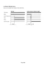
Страница 107: ...Page 106 11 4 Burner Start Up Cycle Lock out is indicated by a lamp on the control box...
Страница 122: ...Page 121 14 SPARES 14 1 RDB 2 2 BX Spares...
Страница 124: ...Page 123 14 2 RDB 3 2 BX Spares...
Страница 134: ...Page 133 Intentionally left blank...
Страница 135: ......


