background image

installation and 
servicing

Mexico Super

Your Ideal installation and servicing guide

See reverse for 

Mexico Super

 users guide

ENGINEERED FOR PEACE OF MIND

When replacing  any part on this appliance use only spare parts that you can be 
assured conform to the safety and performance specification that we require. Do not 
use reconditioned or copy parts that have not been clearly authorised by Ideal Boilers.

RS440, RS450 RS460 & RS470

May 2004   UIN 200 941 A02

200941-2.pmd

6/2/2004, 9:45 AM

1

Содержание Mexico Super RS440

Страница 1: ...ENGINEERED FOR PEACE OF MIND When replacing any part on this appliance use only spare parts that you can be assured conform to the safety and performance specification that we require Do not use reconditioned or copy parts that have not been clearly authorised by Ideal Boilers RS440 RS450 RS460 RS470 May 2004 UIN 200 941 A02 ...

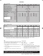
Страница 2: ...3 nett To obtain the gas consumption at a different calorific value a For l s divide the gross heat input kW by the gross C V of the gas MJ m3 b For ft 3 h divide the gross heat input Btu h by the gross C V of the gas Btu ft3 c The appliance is preset at the factory to the highest nominal rating The value is used in the UK government s Standard Assessment Procedure SAP for energy rating of dwellin...

Страница 3: ...r operating pressure measure and record Central heating flow temp measure and record Central heating return temp measure and record For combination boilers only Scale reducer n a Hot water mode Heat input n a Max operating burner pressure n a Max operating water pressure n a Cold water inlet temp n a Hot water outlet temp n a Water flow rate at max setting n a For condensing boilers only Condensat...

Страница 4: ...ntral heating systems BS 5546 Installation of gas hot water supplies for domestic purposes 2nd Family Gases BS 5440 1 Flues for gas appliances of rated input not exceeding 60 kW BS 5440 2 Ventilation for gas appliances of rated input not exceeding 60 kW BS 7593 Treatment of water in Domestic Hot Water Central Heating Systems Health and Safety Document No 635 The Electricity at Work Regulations 198...

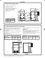
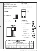
Страница 5: ...ng upon site conditions IMPORTANT In order to facilitate gas connection a clearance of at least 100 mm 4 must be available at either the LH side or the RH side DURING installation Refer to Frame 14 In addition a MINIMUM clearance of 533 mm 21 MUST be available at the front of the boiler for servicing Terminal sizes Boiler Size Depth Height Width RS440 RS450 152 338 372 RS460 RS470 Boiler Size Widt...

Страница 6: ...House Vale Rise Tonbridge Kent TN9 1TB Tel 44 0 1732 359 888 Fax 44 0 1732 354 445 www tfc group co uk Ensure that the guard is fitted centrally 5 Where the terminal is fitted within 1000mm 39 1 2 of a plastic or painted gutter or 500mm 19 1 2 of painted eaves then an aluminium shield at least 1000mm 39 1 2 long should be fitted to the underside of the gutter or painted surface 6 The air inlet pro...

Страница 7: ...hould be at least 1 2 BSP nominal size and be in accordance with BS 2879 If required a drain tap not supplied may be fitted to an unused bottom 1 BSP tapping on the front of the boiler BOILER CONTROL INTERLOCKS Caradon Ideal Limited recommend that heating systems utilising full thermostatic radiator valve control of temperature in individual rooms should also be fitted with a room thermostat contr...

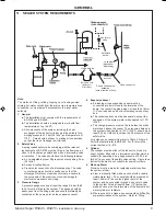
Страница 8: ... to be the highest point of the circulating system 3 The circulating pump is positioned on the FLOW and the vertical distance between the pump and feed expansion tank must comply with the pump manufacturer s minimum requirements to avoid cavitation Should these conditions not apply either lower the pump position or raise the feed expansion tank above the minimum requirements of Caradon Ideal Limit...

Страница 9: ...4 Expansion Vessel a A diaphragm type expansion vessel must be connected at a point close to the inlet side of the pump the connecting pipe being not less than 15mm 1 2 nominal size and not incorporating valves of any sort b The vessel capacity must be adequate to accept the expansion of the system water when heated to 110 o C 230 o F c The charge pressure must not be less than the static water he...

Страница 10: ...between them the stop valve being located between the system and the automatic air vent The stop valve may remain open during normal operation of the system if automatic water make up is required b Through a self contained unit comprising a cistern pressure booster pump if required and if necessary an automatic pressure reducing valve and flow restrictor The cistern should be supplied through a te...

Страница 11: ...rille Mex 2215 Detail of distributor tube alignment Index mark on section boss Distributor tube LEGEND 1 Heat exchanger assy 2 Front section 3 Middle section 4 Section alignment rings and O rings 5 Back section 6 Thermostat pocket 7 Distributor tube 8 Combustion chamber 12 Collector hood 18 Front plate 24 Gas control valve 28 Gas cock 30 PCB 44 Air flue duct assy 46 Baseplate 49 Flue baffle 68 Phi...

Страница 12: ...70 only 1 off FLUE PACKS Packs B B1 and C contents Flue terminal assembly Sachet of sealing mastic 2 off Wall thickness Flue Dimension duct length X shown above pack Boiler fitted flush with wall Boiler fitted in line with 600 mm kitchen units required 114 to 191 mm 4 1 2 to 7 1 2 up to 125 mm up to 5 C 229 to 305 mm 9 to 12 163 to 242 mm 6 1 2 to 9 1 2 B 318 to 394 mm 12 1 2 to 15 1 2 253 to 332 ...

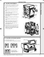
Страница 13: ...or on the PCB lead 4 Remove the Burner On neon cable from the back of the control panel 5 Remove the 2 screws securing the control panel and disengage the panel by lowering and pulling it forward 6 Remove the 2 screws securing the top panel to the side 7 Draw the top panel forward and lift it off the boiler 8 Remove the 2 screws securing the LH side panel to the flue collector and baseplate 9 Pull...

Страница 14: ...ngs Note If using iron elbows fit a short straight connector into the boiler tapping first to clear the casing Connections as viewed at front Thermostat Position Back Section Front Section CH DHW Flow Return Flow Return Top LH LH RH RH LH LH RH RH LH LH RH RH LH LH RH RH LH LH RH RH Table 8 Gravity Domestic Hot Water and Pumped Central Heating 12 PREPARING THE WALL Table 7 Fully Pumped Systems Con...

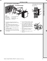
Страница 15: ...ure that the duct is level and make good between the wall and the duct from OUTSIDE of the building 5 From OUTSIDE the building seal the duct join A with the mastic provided 6 From OUTSIDE the building pass the terminal flue duct through the wall opening and slide it into the boiler flue duct pushing the flue duct fully in up to the locating stops Locate it as shown 7 From OUTSIDE of the building ...

Страница 16: ...f any other treatment to this product may render the guarantee of Caradon Ideal Limited INVALID Caradon Ideal Limited recommend Water Treatment in accordance with the Benchmark Guidance Notes on Water Treatment in Central Heating Systems Caradon Ideal Limited recommend the use of Fernox GE Betz Sentinel or Salamander water treatment products which must be used on accordance with the manufacturers ...

Страница 17: ...ons For Ireland reference should be made tot he current ETCI rules for electrical installations The wiring diagrams illustrated in Frames 21 23 cover the systems most likely to be fitted to this appliance For wiring external controls to the Mexico Super 4 RS boiler reference should be made to the system wiring diagrams supplied by the relevant manufacturer in conjunction with the flow wiring diagr...

Страница 18: ...ightly see manufacturer s literature Pumped only LEGEND b blue bk black br brown r red or orange w white gy grey y g yellow green MEX 6037 Room Thermostat Terminal Mid Position valve details Cylinder Thermostat Terminal Boiler supply connector Pump Terminal strip suitably enclosed Typical programmer CH may be selected independently MAINS 20 PICTORIAL WIRING Mex 2554 r r br b b b br bk bk bk br w w...

Страница 19: ...chmaster Autozone has grey and orange auxiliary switch leads but the GREY NOT the orange wire must be connected to the incoming live supply Pumped only 23 HONEYWELL C PLAN Notes 1 Some earth wires are omitted for clarity Ensure proper earth continuity when wiring 2 Numbering of terminals on thermostats is specific to the manufacturer Gravity HW Pumped CH Boiler supply connector Pump Terminal strip...

Страница 20: ...o other wiring of the programmer Designation of the terminals will vary but the programmer and thermostat manufacturer s leaflets will give full details MEX 2181 5 1 Offer up the RH side panel locating it with the peg in the baseplate and push the panel back 2 Secure the panel to the baseplate and collector hood 3 Repeat steps 1 and 2 to refit the LH side panel 4 Place the top panel and push back ...

Страница 21: ...e pilot is established The main burner will then cross light smoothly If this sequence does not occur refer to the Fault Finding section 6 Test for gas soundness around ALL boiler gas components using leak detection fluid 7 Operate the boiler for 10 minutes to stabilise the burner temperature 8 The boiler is preset at the factory to its nominal rating If the burner setting pressure requires adjust...

Страница 22: ...consistent with household requirements of both heating and hot water consumption Advise the User of the precautions necessary to prevent damage to the system and to the building in the event of the system remaining inoperative during frosty conditions Notes If an optional programmer kit is fitted refer to the separate Programmer Kit Installation Instructions and Programmer Kit User s Instructions ...

Страница 23: ...rvicing procedures are covered more fully in Frames 31 35 and MUST be carried out in sequence WARNING Always turn OFF the gas supply at the gas service cock and switch OFF and DISCONNECT the electrical supply to the appliance BEFORE SERVICING IMPORTANT After completing the servicing or exchange of components always test for gas soundness and carry out functional checks as appropriate MEX 1927 6 2 ...

Страница 24: ...ted b The ignition electrode is clean and undamaged c The ignition lead is in good condition and securely connected d The spark gap is correct Refer to Frame 44 5 Clean or renew components as necessary 34 CLEANING THE FLUEWAYS MEX 12182 Reassemble the boiler in the following order 1 Refit the flue cleanout cover renewing any damaged or deteriorating sealing gasket 2 Refit the casing top panel 3 Re...

Страница 25: ...T overtighten 36 GAS PRESSURE ADJUSTMENT 1 Pilot Pressure Pilot adjustment is factory set to maximum and no adjustment is possible 38 SIGHTGLASS REPLACEMENT 39 PILOT BURNER REPLACEMENT 1 Refer to Frame 37 2 Undo the 2 screws lift off the front panel and remove the grille assembly Refer to Frame 31 3 Disconnect the electrical leads from the gas valve 4 Disconnect the ignition lead from the PCB 5 Un...

Страница 26: ...tat 11 Fit the new thermostat and reassemble in reverse order Thermostat bracket Control thermostat Mex 2198 10 7 3 4 6 9 8 Cover 41 IGNITION LEAD REPLACEMENT 1 Refer to Frame 37 2 Remove the 2 screws lift off the front panel and remove the grille assembly Refer to Frame 31 3 Disconnect the electrical leads from the gas valve 4 Disconnect the ignition lead from the PCB 5 Undo the gas cock union Re...

Страница 27: ...ostat phial into pocket and secure with the split pin Thermostat bracket Control thermostat Mex 2184 9 8 3 5 7 Clamp 43 OVERHEAT THERMOSTAT REPLACEMENT if fitted 1 Refer to Frame 37 2 Remove the 2 screws and lift off the lower front panel Refer to Frame 31 3 Slacken the screw at the thermostat pocket and withdraw the phial from the pocket 4 Remove the thermostat retaining nut and withdraw the ther...

Страница 28: ...and withdraw the burner and controls assembly complete from the boiler 6 Remove the 2 screws securing the pilot burner and pull the assembly clear of the main burner 7 Remove the 2 nuts and washers securing the burner to the front plate and manifold Withdraw the burner 8 Fit the new burner and reassemble in reverse order taking care not to damage the main burner injector which is screwed into the ...

Страница 29: ...rew the burner injector from the manifold 9 Fit the new injector using an approved jointing compound and reassemble in reverse order 1 Refer to Frame 37 2 Remove the 2 screws lift off the lower front panel then remove the grille assembly Refer to Frame 31 3 Disconnect the electrical leads from the gas valve 4 Disconnect the ignition lead from the PCB 5 Undo the gas cock union Remove the 4 wing nut...

Страница 30: ...front panel Refer to Frame 31 3 Undo the PCB cover fixing screw and remove the cover 4 Remove the HT lead from the PCB 5 Remove the 6 push in connectors from the PCB 6 Compress the barbs on the PCB stand offs to release the PCB from the box 7 Fit the new PCB and reassemble in reverse order 8 Refit the boiler casing 9 Check the operation of the boiler MEX 2325 6 4 3 5 ...

Страница 31: ...wn Reset the overheat stat Set control stat to maximum Allow the boiler to reach temperature if the overheat stat trips again measure flow temperature If above 90 C replace control stat If below 90 C replace overheat stat YES Is there a spark at the ignition electrode Does the pilot burner light NO Is there a gas supply to the boiler has the gas supply been purged of air Connect or rectify and pur...

Страница 32: ...27 E26 397 HT lead 900 mm 1 058 826 30 H20 882 PCB25E 1 173 799 66 E05 070 Thermostat 1 151 903 67 308 557 Thermostat knob 1 111 904 The following are parts commonly required as replacement components due to damage or expendability Their failure or absence is likely to affect safety or performance of this appliance The list is extracted from the British Gas List of Parts which contains all availab...

Страница 33: ...33 Mexico Super RS440 470 Installation Servicing LISTOFP ARTS 48 SHORT PARTS 17 20 21 22 23 24 30 67 66 26 27 Mex 1949 ...

Страница 34: ...ont panel door 72 Magnetic strip Thermostat nut Thermostat bracket Mex 2214 Cable clamps PCB lead 71 72 67 64 65 66 Cover 50 BOILER CONTROL PANEL Exploded View Legend 46 Baseplate 62 Casing complete 63 Controls panel complete 73 Side panel 75 Casing front panel 76 Top panel 77 Grille assy 78 Casing fixing pack not shown 49 BOILER CASING ASSEMBLY Mex 1953 76 63 77 46 73 75 73 ...

Страница 35: ...d 16 Front plate assy 17 Sightglass assy 18 Burner manifold assy 19 Pilot burner pipe 20 Main burner 21 Main burner injector 22 Pilot burner assy 24 Gas valve 25 O ring 26 Ignition electrode 27 HT lead 28 Gas cock 50 Sealing plate gasket 51 Sealing plate 52 PCB BOX Exploded View Legend 29 PCB chassis assy 30 PCB sub assy 33 PCB support 37 PCB cover 33 29 30 37 MEX 2324 ...

Страница 36: ...of first class training courses for domestic commercial and industrial heating installers engineers and system specifiers For details of courses please ring 01482 498 432 THIS SYMBOL IS YOUR ASSURANCE OF QUALITY These appliances are designed for use with Natural Gas only They have been tested and conform with the provisions of BS 6332 and BS 5258 CERTIFIED PRODUCT Manufactured under a BS EN ISO 90...

Отзывы: