WAGO-I/O-SYSTEM 750
Function Description
45
750-636/000-x00 DC Drive Controller 24V/5A
Manual
Version 2.1.0
4.12 Swing-Back Drives with Subsequent Setpoint
Position Drive
The I/O module only starts a braking process from the CurrentControl_PWM or
the maximum speed, but never from the CurrentLimit_PWM. This should be
taken into account when designing the project. The result is a positioning process
optimized for time or distance. The swing-back drive takes into account both
phase P1 and phase P2. For particularly slow loads, Increase_Swing_Back
(swing-back extension) should be increased based on the factor. This causes an
artificial extension of the swing-back drive, so that the drive can achieve its
maximum speed or the configured CurrentControl_PWM speed before the
setpoint position drive is introduced. If this is not taken into account in the project
design, the positioning process may not be optimized for time and distance in all
process situations.
Again here, if the acceleration distance is shorter than the braking distance, then
the value of the braking distances is used for the acceleration distance.
Swing-back distance = ((acceleration di braking distance) * 110%) *
(100% + X%)
Calculating the swing-back distance!
The swing-back distance is used to determine if the drive is far enough away from
the setpoint position so that this can be reached. Depending on the result, a
setpoint position or switch-back drive must be started!
4.12.1 Definition of the Swing-Back Drives
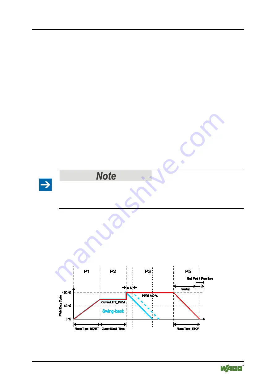
In the representation below, no CurrentControl_PWM is enabled because
ShutDown_Distance is not enabled, and the drive is always stopped from 100%
PWM with large setpoint position drives (red line). So that the 100% PWM phase
is also reached for short distances during a positioning process, the represented
swing-back drive is always executed at a minimum (blue line).
Figure 31: Braking from 100% PWM
A similar behavior appears when the phase P4 has to be driven with
CurrentControl_PWM based on a configured ShutDown_Distance. In this case, it


