


Section 7 —Disassembly
Page 7-20
VitalCare
TM
506N3 Series
Service Manual
Criticare Systems, Inc.
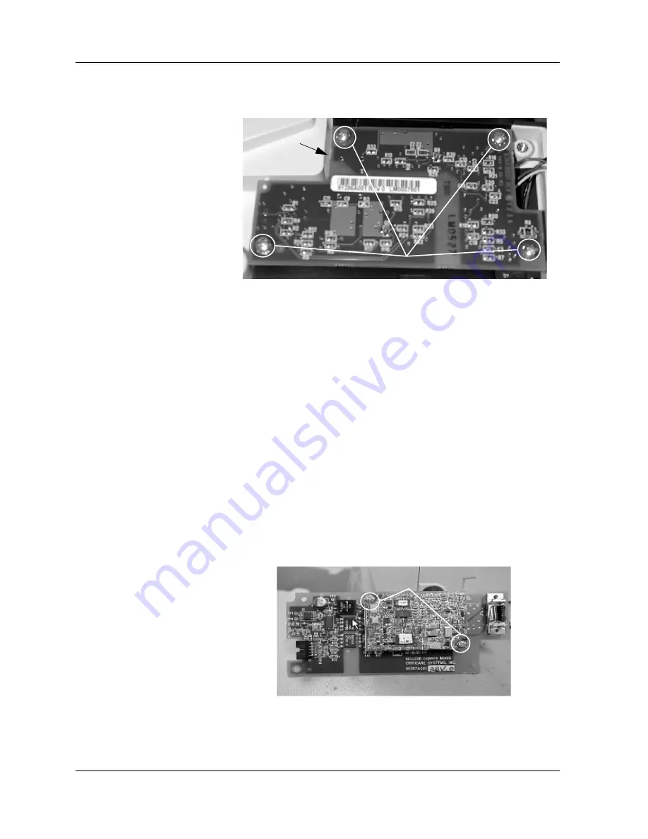
4. Remove the four (4) screws (pn 40995B005) from the FasTemp
Isolation PCB.
Figure 7-26: Remove Isolation Board Screws
5. Carefully lift up the Isolation PCB (pn 91386A001).
6. Remove the Temp cable (pn 90931A001) from the connector
beneath the PCB.
NOTE
: Do not tuck temp cable into opening. Add RTV to the
connector after reassembly.
7. Remove the standoffs (pn 42476B001) that are holding the
insulator PCB. Torque is 2 in. lbs.
NOTE
: Insulator is placed first, then standoffs.
8. Remove the insulator.
9. Remove the two (2) screws (pn 40995B005) that are holding the
Nellcor Carrier PCB (pn 91387A001) to the base assembly.
Torque is 5 in. lbs.
10.Unplug the SpO
2
cable (pn 90930A001) from
P1
of the PCB.
11.Remove the two (2) screws (pn 41258B003) from the top of the
PCB. Torque is 2 in. lbs.
Figure 7-27: Removing Carrier PCB
12.Lift the Nellcor PCB (pn 83459B001) up from its connectors.
Remove Screws (torqued @ 5 in lbs)
Temp cable
underneath PCB
Remove Screws
Содержание 506DN3
Страница 12: ......
Страница 56: ......
Страница 62: ......
Страница 90: ......
Страница 156: ......
Страница 184: ......
Страница 225: ......
Страница 229: ......
Страница 230: ......
Страница 231: ......
Страница 232: ......
Страница 233: ......
Страница 237: ......
Страница 238: ......
Страница 239: ......
Страница 240: ......
Страница 241: ......
Страница 242: ......
Страница 243: ......
Страница 244: ......
Страница 245: ......
Страница 247: ......
Страница 248: ......
Страница 249: ......
Страница 250: ......
Страница 251: ...DO NOT SCALE PRINT DO NOT SCALE PRINT REV DATE DESCRIPTION BY...
Страница 253: ......
Страница 254: ......


