background image

 Product Description

2-3

Strata RX

 Operator’s Guide/Tech Ref Manual

Analog or Digital Demodulation Only  

If you are integrating 

the RX System into existing equipment and need only the 
demodulation functions, your RX will have only an RCU. The 
RCU can be equipped with an analog demodulator, a digital 
demodulator, or both. When the optional MPEG decoder is also 
installed, the system includes a color bar generator. The RCU 
also contains a Low Pass Filter, which is always in the video 
signal path.

Since the switchable IF filters are in the RXU, this capability is 
not part of the demodulator-only system.

2.2.2

Antenna and Power Options  

The flexible architecture of the Strata RX allows a number of 
options for both the receive antenna and the power.

Antenna Options  

The Strata RX is fully compatible with 

Vislink’s families of receive antennas, including:

OmniPole omnidirectional

Megahorn compact horn

SectorScan flat panel

MicroScan  parabolic

Ellipse parabolic

Contact your Sales Representative to explore the wide array of 
antenna choices available.

Power Options  

The Strata RX system runs on DC power 

supplied externally, from +10.5 VDC to +36 VDC. This can be 
supplied by the optional Strata ACU power supply, or from 
another source. Certain other voltages can be accommodated by 
special request; contact your Sales Representative for the latest 
details.

If the RXU and RCU are located together, power is usually 

supplied to each unit through its power connector, from the same 
power source. See Figure 2-1.

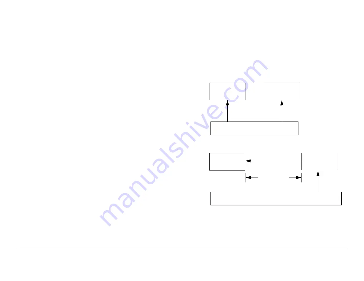
If your installation calls for separating the RXU and RCU, the 
RXU is powered by DC supplied by the RCU via the coaxial 
cable between the units. See Figure 2-2.

Refer to the “Installation” chapter of the 

Strata RX Technical 

Reference Manual

  for more information.

Figure 2-1: Powering the RXU and RCU Independently

Figure 2-2: Powering the RXU from the RCU

Strata RXU

Strata RCU

DC Power (+10.5 V - +36 V)

Power 
Cable

Power 
Cable

Strata RXU

Strata RCU

DC Power (+10.5 V - +36 V)

up to 600’
(200 m)

Coax

Power 
Cable

Содержание Strata RX

Страница 1: ...g Digital Portable Microwave Receiver Technical Reference Manual RXU RX AUDIO SIGNAL OUTPUT PWR RS 485 PWR STRATA STRATA RCU RCU RX RX DC DC ON COAX ON COAX OFF OFF ON ON STRATA STRATA Manual Part No 400495 2 Rev A July 2004 ...

Страница 2: ......

Страница 3: ...ser to the extent needed for their organization No part of this material may be modified in any way or published for resale without the express written authorization of Vislink plc 2004 Vislink plc Worldwide Headquarters Vislink plc Nashleigh Hill Chesham Buckinghamshire HP5 3HE England Tel 44 0 1494 774400 Fax 44 0 1494 791127 US Support Centre Microwave Radio Communications 101 Billerica Avenue ...

Страница 4: ...esign improvements specifications are subject to change without notice Conventions Pay special attention to information marked in one of the following ways CAUTION Follow CAUTIONS closely to prevent personal injury or death WARNING Follow WARNINGS to prevent damage to the equipment Note Notes provide additional information to assist you in using and maintaining the equipment On Line Viewing Text d...

Страница 5: ... workmanship provided Buyer has promptly reported same to Vislink in writing All replaced products and parts will become Vislink s property c Vislink will honor the warranty at the repair facility designated by Vislink It is Buyer s responsibility to return at its expense the allegedly defective product to Vislink Buyer must obtain a Return Material Authorization RMA number and shipping instructio...

Страница 6: ...fic product a written request should be made to Vislink All Products THE FOREGOING WARRANTIES AND REMEDIES ARE EXCLUSIVE AND ARE IN LIEU OF ALL OTHER EXPRESS OR IMPLIED WARRANTIES OBLIGATIONS AND LIABILITIES ON THE PART OF VISLINK EXCEPT FOR THE EXPRESS WARRANTIES STATED HEREIN VISLINK DISCLAIMS ALL WARRANTIES ON PRODUCTS FURNISHED HEREUNDER INCLUDING WITHOUT LIMITATION ALL IMPLIED WARRANTIES OF M...

Страница 7: ...ts 2 4 Strata RXU 2 5 Strata RCU 2 5 Controls and Connections 2 5 Typical System Configurations 2 6 For More Information 2 14 Routine Operation 3 1 Chapter Overview 3 1 Overview of Controls 3 1 Power Switch 3 1 Status LED 3 2 Alphanumeric Display 3 2 Control Switch 3 2 Using the Strata RX Screens 3 3 DC on Coax Switch 3 4 Preparing for Operation 3 6 Setting Up 3 6 Turning the power ON and OFF 3 8 ...

Страница 8: ...ng Page 5 14 Using the Monitoring Page 5 15 Front Panel vs Configurator Settings 5 18 Installation 6 1 Chapter Overview 6 1 Unpacking 6 1 Initial Inspection 6 1 Damage in Shipment 6 1 Mounting and Cabling 6 2 Floor Bulkhead Installation 6 2 Tripod Deployment 6 3 Power Connections 6 4 Power Requirements 6 4 Power Supply and Distribution 6 4 Additional Powering Notes 6 6 Grounding 6 7 Audio Connecti...

Страница 9: ...view C 1 Working With the Configurator C 1 Tabs Pages and Buttons C 1 Progress Bars C 3 Load and Program Options C 4 Configurator Pages C 6 Main Page C 6 Radio Page Standard C 7 Radio Page Frequencies Locked to Presets C 8 COFDM Page C 9 MPEG Page C 9 FMR Page C 11 Channel Plan Page C 13 Front Panel vs Configurator Settings C 14 Configurator Troubleshooting C 17 Configurator Error Messages C 17 Co...

Страница 10: ...Contents viii Strata RX Technical Reference Manual ...

Страница 11: ...a RX System are organized as follows Chapter Operator s Guide Technical Reference Manual Introduction Product Description Routine Operation Advanced Operation Note The Technical Reference Manual contains everything in the Operator s Guide plus additional technical content 1 4 Who It s Written For This manual is intended for use by qualified installers and technical personnel Users of this manual s...

Страница 12: ...s on the display at startup 1 7 Calling for Service Technical Support is available 24 hours a day 7 days a week through Vislink Communications Ltd s US Support Centre During regular business hours you can reach our expert staff directly After hours your call will be forwarded to the on call technical support specialist Business Hours Monday 8 00 AM 5 00PM Eastern Time US 0800 1700 hrs US ET Tuesda...

Страница 13: ... repair If you attempt field repair you risk damaging your radio If the radio is under warranty you may also affect your warranty coverage 1 9 Tell Us What You Think We d love to receive any comments or suggestions you have about this manual The more feedback we get the better the manuals get If you re viewing this manual electronically it s easy just click on the link below send us an email Or yo...

Страница 14: ...Introduction 1 4 Strata RX Technical Reference Manual ...

Страница 15: ...Demodulation Options Bands The RX System can be ordered configured for any one of several RF bands In addition selected combinations of band segments are available in a two band version We are constantly working to expand and upgrade the capabilities of the RX System Consult your Sales Representative or contact the factory for the latest band availability RF IF Only If you are integrating the RX S...

Страница 16: ...Hz IF output The RCU contains a COFDM demodulator and can include an MPEG decoder When equipped with an MPEG decoder the system also includes a color bar generator The RCU provides either composite or digital video output with either digital or analog audio or both Used for situations where the RCU and RXU must be deployed in different locations up to 600 200 m apart RF Analog Digital Demodulation...

Страница 17: ...n SectorScan flat panel MicroScan parabolic Ellipse parabolic Contact your Sales Representative to explore the wide array of antenna choices available Power Options The Strata RX system runs on DC power supplied externally from 10 5 VDC to 36 VDC This can be supplied by the optional Strata ACU power supply or from another source Certain other voltages can be accommodated by special request contact...

Страница 18: ...ware preset configurations current status and alarms System Operation Once the RXU and RCU are connected and communicating the units work seamlessly together System settings can be selected and modified from the front panel of either unit regardless of which unit holds the hardware being configured System Configuration The Strata RX offers two levels of system configuration designed to match the n...

Страница 19: ...the following additional features a wayside data channel capable of data rates from 1200 to 38 400 baud a configurable Monitor output which can provide either 70 MHz or ASI output 2 4 Controls and Connections Front and rear views of the Strata RXU and RCU are shown in the pages that follow under Typical System Configurations For details on the connections refer to the Strata RX Technical Reference...

Страница 20: ...esent but not functional GEN LOCK Connector If your RXU or RCU has COFDM MPEG installed this rear panel input allows you to supply an external synchronization signal 400 mV p p nominal to the MPEG decoder The RX System must be configured to use this signal using the RX configurator software If the System is configured to accept a GEN LOCK signal and none is present the MPEG decoder will automatica...

Страница 21: ...ion 2 7 Strata RX Operator s Guide Tech Ref Manual Figure 2 3 RF IF Only RXU SYSTEM OUTPUT SYSTEM INPUT RF from Antenna 70 MHz IF RF Front End 70 MHz IF MON RXU RX AUDIO SIGNAL OUTPUT PWR RS 485 PWR RS 232 MON GEN LOCK ...

Страница 22: ...Figure 2 4 RF Analog Demodulation RXU only RXU SYSTEM OUTPUT RF from Antenna RF Front End MON Analog Demod NTSC or PAL Composite Video NTSC or PAL 4 channels Analog Audio SYSTEM INPUT RS 232 MON GEN LOCK RXU RX AUDIO SIGNAL OUTPUT PWR RS 485 PWR STRATA STRATA 70 MHz IF ...

Страница 23: ...End MON 70 MHz IF Analog Demod NTSC or PAL MON Composite Video NTSC or PAL 4 channels Analog Audio RXU SYSTEM OUTPUT RCU SYSTEM INPUT RXU RX AUDIO SIGNAL OUTPUT PWR RS 485 PWR RS 232 MON GEN LOCK RCU RCU RX RX DC DC ON COAX ON COAX OFF OFF ON ON STRATA STRATA POWER RS 485 SIGNAL IN AUDIO SIGNAL OUTPUT MON GEN LOCK 70 MHz IF 70 MHz IF ...

Страница 24: ...End 70 MHz IF or ASI MON RS 232 MON GEN LOCK RXU RX AUDIO SIGNAL OUTPUT PWR RS 485 PWR STRATA STRATA RXU SYSTEM OUTPUT SYSTEM INPUT SDI or ASI output of COFDM demod or External IF or Composite Video NTSC or PAL Digital Demod COFDM MPEG 4 Channels analog audio or 2 Channels analog audio 2 Channels digital audio or 4 channels digital audio ...

Страница 25: ...UT RCU SYSTEM INPUT RXU RX AUDIO SIGNAL OUTPUT PWR RS 485 PWR RS 232 MON GEN LOCK RCU RCU RX RX DC DC ON COAX ON COAX OFF OFF ON ON STRATA STRATA POWER RS 485 SIGNAL IN AUDIO SIGNAL OUTPUT MON GEN LOCK Digital Demod COFDM MPEG SDI or ASI output of COFDM demod or External IF or Composite Video NTSC or PAL 4 Channels analog audio or 2 Channels analog audio 2 Channels digital audio or 4 channels digi...

Страница 26: ...PUT SYSTEM INPUT RXU RX AUDIO SIGNAL OUTPUT PWR RS 485 PWR RS 232 MON GEN LOCK RCU RCU RX RX DC DC ON COAX ON COAX OFF OFF ON ON STRATA STRATA POWER RS 485 SIGNAL IN AUDIO SIGNAL OUTPUT MON GEN LOCK 70 MHz IF 70 MHz IF Digital Demod COFDM MPEG SDI or ASI output of COFDM demod or External IF or Composite Video NTSC or PAL 4 Channels analog audio or 2 Channels analog audio 2 Channels digital audio o...

Страница 27: ... COAX OFF OFF ON ON STRATA STRATA 70 MHz IF Can be equipped with either analog or digital demodulators or both Only present with MPEG decoder POWER RS 485 SIGNAL IN AUDIO SIGNAL OUTPUT MON GEN LOCK Digital Demod COFDM MPEG SDI or ASI output of COFDM demod or External IF or Composite Video NTSC or PAL 4 Channels analog audio or 2 Channels analog audio 2 Channels digital audio or 4 channels digital ...

Страница 28: ...trata RX can be found in the Strata RX Technical Reference Manual Specific topics are listed below Topic Chapter Installation Installation Connections to other equipment Installation Changing settings using the Configurator software Advanced Operation Block Diagram Theory of Operation Supported Repairs Repair Repair Parts Replacement Parts ...

Страница 29: ...ngs 3 30 3 2 Overview of Controls This section describes the controls and indicators used on the RXU and RCU Here are the topics covered Each of these is described in more detail in the sections that follow Front panel views of the RXU and RCU are shown in Figure 3 2 on page 3 5 The RX System may also be configured using Windows PC based configurator software For details see the Strata RX Technica...

Страница 30: ...errors are detected Amber Minor Alarm Power is on but some part of the system reports an abnormal condition that might impair performance Red Major Alarm Power is on but there is a failure or error that prevents normal operation 3 2 4 Control Switch Routine operating settings are controlled by the Control Switch See Figure 3 2 on page 3 5 Turning the Control Switch right or left displays status an...

Страница 31: ...o the Main Screen 3 2 5 Using the Strata RX Screens As you use your Strata RX you will interact extensively with the screens and menus Following are some points to make this easier Main Screen The Main Screen is your starting point for navigating through the Monitor and Command screens The Main Screen provides the current values of Preset signal strength and Link Quality When the Strata RX is fini...

Страница 32: ...alled in that individual unit When you connect your RCU and RXU the two units automatically detect what hardware is installed in which unit and automatically configure the menus and options to match the installed hardware The connected RX System then allows you to control the entire system from either front panel regardless of what hardware is installed in which unit 3 2 6 DC on Coax Switch The St...

Страница 33: ...s Guide Tech Ref Manual Figure 3 2 Front view RXU and RCU RCU RCU RX RX DC DC ON COAX ON COAX OFF OFF ON ON STRATA STRATA RXU RX AUDIO SIGNAL OUTPUT PWR RS 485 PWR STRATA STRATA Display Control Switch Power Switch Status LED DC On Coax Switch ...

Страница 34: ...Dovetail Adapter Plates that will convert some types of tripods to accept the Quick Release Figure 3 3 Fixed Mounting Bracket on Tripod Portable Deployment For portable applications where the Strata RX will be moved from place to place and set up each time the RX will usually be mounted in a Vislink Universal Mounting Bracket The Bracket will then be attached to a Quick Release for easy mounting o...

Страница 35: ...tenna See Figure 3 6 3 If you have both an RXU and an RCU be sure they Universal Mounting Bracket Mounting Plate for RXU RCU Quick Release Vislink Tripod are connected to each other via coaxial cable If you are unsure of the connections refer to the Installation chapter of the Strata RX Technical Reference Manual 4 Connect the Strata RXU and RCU if present to DC power of the correct voltage and po...

Страница 36: ...minate and change colors from red to green to amber and finally green The display should light up and display first a self test screen then the version of the installed firmware and finally the Main Screen Some typical screens are given in Figure 3 7 The exact screens will vary depending on installed hardware The RX System will typically power up using the last settings in use when power was turne...

Страница 37: ...l appear are Main Screen RF Input Signal Error Code See Figure 3 8 for an overview of what is reported on these Monitor Screens Settings vs Detected Values vs Measured Values In External IF operation all but one of the values in the Monitor screens are settings that are configured in the RX The only measured value is the incoming signal strength There are no values that are detected and automatica...

Страница 38: ...l operation there are four types of values reported on the Monitor Screens Detected values which the RX senses and automatically configures to match the parameters of the incoming signal Detected values are Modulation FEC Forward Error Correction GI Guard Interval Audio Type Settings which are configured in the RX and must be manually set to match the incoming signal Settings are Preset Band Chann...

Страница 39: ... 4 ON RF Input Signal Audio 1 Audio 2 Audio 3 Audio 4 Video Audio Emphasis 1 2 Audio Emphasis 3 4 Error Code Main Screen Monitor Screens Analog Ext IF Ext IF IF Fil Ana Analog FM IF Fil Ana TURN to select PUSH to hold Analog Ext IF Digital Common Band Channel Frequency MHz Audio Channel De Emphasis ON OFF Video Deviation MHz Video Mute Status ON OFF Operating Mode External IF or Analog IF Filter A...

Страница 40: ...No Errors Color Bar Error Code Main Screen Digital Audio Data Status Lock Unlock Audio Type Analog Digital Stereo Mono Video Output Setting CV Composite Video Video Data Status Locked Yes No Preset Received Carrier Level RF Band Channel Frequency MHz Link Quality Reading Pre Viterbi Bit Error Ratio Post Viterbi Bit Error Ratio COFDM Status LOCK UNLOCK Transport Stream Status LOCK UNLOCK Color Bar ...

Страница 41: ...Link Quality Vislink has developed the Link Quality indicator to give you back that early warning of an analog system Link Quality monitors several key parameters and uses proprietary algorithms to derive one simple indication of digital signal quality The Link Quality algorithms report one LQ Link Quality result scaled from 0 to 9 as shown in Table 3 1 For more information on Link Quality refer t...

Страница 42: ...screen on the display do the following Push the Control Switch to lock the display on this screen Data on display will continue to update To allow the display to show other screens do the following Push the Control Switch to unlock the display Preset 3 43 2 dBm LQ7 you do based on your experience 3 4 6 What Actions to Take To improve the Link Quality we suggest the following general sequence of ac...

Страница 43: ...solate noise sources by shutting down other equipment 3 Optimize BER No signal Check the COFDM BW setting to be sure it matches the incoming signal Change transmit settings to make the link more robust You will achieve a lower Data Transfer Rate as you do so See Table 3 3 Note Factory default settings are highlighted in green The receiver will automatically adjust for the new settings Note BW must...

Страница 44: ... uncorrected errors will then appear in the Post Viterbi BER These Post Viterbi errors are a warning sign even though the video may still be acceptable If the Post Viterbi BER becomes too large the MPEG decoder will be unable to make sense of the data and video will be lost Error Bits Detected Total bits received PRE 2 0E 7 POST 0 0E 7 Monitoring the BER screen will help you be aware of this signa...

Страница 45: ...sure Strata is connected and powered See Setting Up and Turning the power ON and OFF Start at the Main Screen Turn the Control Switch RIGHT until the display shows the SNR Monitor Screen It will be similar to this Overall Signal Strength Detected Noise Preset 3 43 2 dBm SNR 20 78 dB IF Filter Dig To lock this screen on the display also do the following Push the Control Switch to lock the display o...

Страница 46: ...t contains most of the operating settings needed to control the RX System including digital or analog demodulation digital or analog video and audio outputs Presets must be preconfigured using the Strata RX Configurator software Once defined the details of a Preset cannot be changed from the RX front panel For information on configuring Presets see the Configurator Reference chapter of the Strata ...

Страница 47: ...the power ON and OFF Start at the Main Screen Turn the Control Switch LEFT until the display reads Chng Preset Push the Control Switch to select Chng Preset The current Preset setting begins to blink Turn the Control Switch LEFT until the desired Preset is displayed Push the Control Switch to select that Preset Display changes back to the Main Screen Newly selected Preset should appear Preset 43 2...

Страница 48: ... steps Be sure Strata is connected and powered See Setting Up and Turning the power ON and OFF Start at the Main Screen Turn the Control Switch LEFT until the display reads Set Channel Preset 3 43 2 dBm To check that the channel has changed correctly follow these steps Frequencies Locked to Presets If your RX has the Frequencies Locked to Presets option enabled the Frequency that is locked to a gi...

Страница 49: ...and Offsets This means that if for example your RX is set to Channel 1 on the 2 GHz Band and the Band is changed to 7 GHz the RX will now be set to Channel 1 as defined in the 7GHz Channel Plan To select which Band to use follow these steps Be sure Strata is connected and powered See Setting Up and Turning the power ON and OFF Start at the Main Screen Preset 3 43 2 dBm Note If your RX System conta...

Страница 50: ...e system performance will be degraded To select the IF Filter setting follow these steps Be sure Strata is connected and powered See Setting Up and Turning the power ON and OFF Start at the Main Screen Turn the Control Switch LEFT until the display reads Set IF Filter The display will also indicate Ana or Dig Push the Control Switch to change the Filter setting Preset 3 43 2 dBm Note If your RX Sy...

Страница 51: ...Monitor connectors on the two units provide the following RXU Monitor always provides 70 MHz IF RCU Monitor is switchable between 70 MHz IF and ASI To select the Monitor output follow these steps Be sure Strata is connected and powered See Setting Up and Turning the power ON and OFF Start at the Main Screen Preset 3 43 2 dBm Note If your RX System contains only an analog demodulator the front pane...

Страница 52: ...to external equipment External IF mode To set the Squelch level follow these steps Be sure Strata is connected and powered See Setting Up and Turning the power ON and OFF Start at the Main Screen Turn the Control Switch LEFT until the display reads Squelch Adj Push the Control Switch to select Squelch Adj The current Squelch setting begins to blink Preset 3 43 2 dBm Turn the Control Switch LEFT un...

Страница 53: ...se steps Be sure Strata is connected and powered See Setting Up and Turning the power ON and OFF Start at the Main Screen Turn the Control Switch LEFT until the display reads Set OFDM BW Push the Control Switch to select Set OFDM BW The current Bandwidth setting begins to blink Turn the Control Switch LEFT until the desired Bandwidth is displayed The choices are 6 MHz 7 MHz 8 MHz Preset 3 43 2 dBm...

Страница 54: ...RX Technical Reference Manual for more details Two step control To prevent inadvertent damage to test equipment that may be connected to the coaxial cable there is a two step control for the DC Power applied to the coax To enable DC Power on the coax both of the following must be done The DC ON COAX switch on the front of the RCU must be set to ON AND The System must be configured to have DC on th...

Страница 55: ...3 6 Front Panel Menu Maps Following are one page menu maps to help you navigate through the settings available using the front panel Control Switch For information on settings available when using the Strata RX Configurator see the Strata RX Technical Reference Manual ...

Страница 56: ...Lock Analog Mono ClrBar OFF RF Input Signal BER SNR COFDM Video Audio A Audio B No Errors Color Bar Error Code Audio 1 OFF Freq 4 83MHz Audio 2 OFF Freq 4 83MHz Audio 3 OFF Freq 4 83MHz Audio 4 OFF Freq 4 83MHz Vid Dev 4MHz Vid Mute OFF Aud De emph 1 ON 2 ON Aud De emph 3 ON 4 ON RF Input Signal Audio 1 Audio 2 Audio 3 Audio 4 Video Audio Emphasis 1 2 Audio Emphasis 3 4 Error Code Main Screen Moni...

Страница 57: ...t Channel Channel 2 Channel 1 2 3 10 14 75 Ohm Coax Power OFF 75 Ohm Coax Power ON Set IF Filtr IF Fil Ana Set IF Filtr IF Fil Dig Set Monitor 70 MHz Out Set Monitor ASI Out 6 7 8 MHz Set OFDM BW 8 MHz Main Screen Preset Channel Band IF Filter Monitor Squelch Analog Ext IF only COFDM Digital only DC Power Command Screens WARNING Turn off DC Power on Coax BEFORE connecting test equipment TURN to se...

Страница 58: ...Configurator A summary of which settings can be controlled by each method is in Table 3 4 Table 3 4 Front Panel vs Configurator Settings Parameter Available Settings Set Using Control Switch Set Using Config urator Presets Preset in use 1 2 9 Preset text Any 12 alphanumeric characters Operation Mode MPEG CV Out ASI Out SDI Out Ext IF FM CV Out IF Filter in use Analog Digital Squelch level No Squel...

Страница 59: ...C On Coax On Off COFDM COFDM Bandwidth 6 MHz 7 MHz 8 MHz Table 3 4 Front Panel vs Configurator Settings Continued Parameter Available Settings Set Using Control Switch Set Using Config urator MPEG Gen Lock Selected Not selected NTSC Pedestal Selected Not selected Audio Output Analog AES EBU Color Bars On Off BISS Encryption On Off Table 3 4 Front Panel vs Configurator Settings Continued Parameter ...

Страница 60: ...requency 4830 kHz 5200 kHz 5800 kHz 6200 kHz 6800 kHz 7020 kHz 7500 kHz 8065 kHz 8300 kHz 8590 kHz Audio Channel Enabled Selected Not selected Deemphasis Selected Not selected Filtered Selected Not selected Table 3 4 Front Panel vs Configurator Settings Continued Parameter Available Settings Set Using Control Switch Set Using Config urator ...

Страница 61: ...e a potential safety hazard Shut down the RX System and disconnect power Table 4 1 Status LED Indications LED Color Meaning Suggested Action Power is not on in that unit Turn on Power Green Power is on and no errors are detected None Amber Minor Alarm Power is on but some part of the system reports an abnormal condition that requires attention Condition might impair performance Check Monitor Scree...

Страница 62: ...ch Ref Manual 4 3 Messages on Display One of the ways the RX will alert you to problems is by messages on its front panel display These are displayed on the Monitor Screens See Table 4 2 for descriptions of the messages and what to do when they appear ...

Страница 63: ...fered internal failure Send unit for service RF NOT FOUND The RCU is not detecting the RF section of the RXU In an RCU only system this is normal there is no RXU to detect None If error persists RF hardware may have failed Send unit for service In a system with both RXU and RCU Check connection between RXU and RCU Use Monitor Radio feature of Configurator to list errors Use Configurator to check s...

Страница 64: ...u to investigate the problem The Error Codes are formatted into 2 groups of characters as described in Figure 4 1 Figure 4 1 Error Code Format 4 4 1 Primary Error Code The first group of characters is the Primary Error Code In most cases this portion of the Error Code will uniquely identify the problem See Table 4 3 for descriptions of the error codes and what to do when they appear E141 45 Primar...

Страница 65: ...he settings in the radio If problem persists possible hardware failure Send unit for service E201 FMR Audio 2 PLL Unlocked E202 FMR Audio 3 PLL Unlocked E203 FMR Audio 4 PLL Unlocked E204 FMR Audio 1 No Sub Carrier Detected Check to be sure transmitter is operating If not transmitting this is normal there is no subcarrier to detect Check subcarrier frequencies using Monitor Screens Subcarrier freq...

Страница 66: ...e settings in the radio If problem persists possible hardware failure Send unit for service E121 MPEG Video Lock Alarm E122 MPEG PCR Lock Alarm E140 Block Down Converter PLL Unlocked E141 Low Noise Down Converter PLL Unlocked E142 IF PLL Unlocked Parameter Errors Some internal parameter is outside of allowable limits E150 RXU 2 048 volt reference error Check for Error Codes related to power E156 E...

Страница 67: ...See Section 3 4 6 on page 3 14 Call for technical service If errors persist when tested on service bench with known good signal source unit has suffered internal failure Send unit for service E155 RXU Temperature error Check RX to be sure it is not too close to sources of heat Relocate RX if possible Check to be sure RX has room around it for air circulation Move objects preventing air flow Call f...

Страница 68: ...rcular Connector Current error Make sure all power cables are connected properly and are not damaged Call for technical service If errors persist with correct power connected unit has suffered internal failure Send unit for service E15A RXU Circular Connector Voltage error E15B RXU Circular Connector Power error E1F0 RCU 2 048 volt reference error Check for Error Codes related to power E156 E158 a...

Страница 69: ...t cable and connectors are undamaged Make sure all power cables are connected properly Call for technical service If errors persist with correct coax connections and correct power connected unit has suffered internal failure Send unit for service E1F6 RCU 75 Ohm Coax Voltage error E1F7 RCU 75 Ohm Coax Power error E1F8 RCU Circular Connector Current error Make sure all power cables are connected pr...

Страница 70: ... a problem See Table 4 5 Table 4 4 Error Status Digit Status Digit Meaning Status Error Error Codes E0F0 E142 8 There is an error Parameter Error Error Codes E150 E1FA 4 Value is too low 8 Value is too high Table 4 5 Strata Unit ID Digit Unit ID 1 Transmitter Unit TXU 4 Receiver Unit RXU 5 Receiver Control Unit RCU 4 5 Operational Problems The information on the following pages will assist you in ...

Страница 71: ...eck COFDM Monitor Screen If not locked check COFDM Bandwidth BW setting BW MUST match with incoming signal Use Configurator to check BW settings Be sure BW settings match the transmitter settings Video configuration incorrect Check video settings using Monitor Screens and Command Screens Settings must match transmitter settings Use Configurator to check video settings Be sure all settings match th...

Страница 72: ... Optional BISS Encryption Decryption No video BISS Decryption not operating Use Configurator to check BISS settings Be sure key and or ID match the transmitter settings Table 4 6 Video Problems Continued Problem Possible Cause Suggested Operator Action Suggested Technical Staff Action ...

Страница 73: ...dio settings match transmitter Use Monitor Radio function of Configurator to identify which channel is not working Check audio configuration using Configurator on the MPEG page Settings must match both incoming signal and wiring of RX audio connections Audio subcarrier frequencies not matched to transmitter settings Check subcarrier frequencies using Monitor Screens Subcarrier frequencies must mat...

Страница 74: ...Strata RX does not currently support DVB S audio Reconfigure link to use other audio format Contact Vislink for latest information on availability Linear Audio not being received Strata RX does not currently support Linear audio Reconfigure link to use other audio format Contact Vislink for latest information on availability If Unit Enabled for Optional BISS Encryption Decryption No audio in one o...

Страница 75: ...t for service Changing settings on one unit doesn t change settings on the other in a connected RXU RCU system RXU and RCU are not communicating Check connection between RXU and RCU Turn power off in both RXU and RCU Then turn power back on in both If problem persists with correct coax connections one or both units have suffered internal failure Send units for service Can t find Chroma settings No...

Страница 76: ...Page of Configurator are incorrect RX does not currently support multi service selection PID values shown are fixed Contact Vislink for latest information on availability Table 4 8 General System Problems Continued Problem Possible Cause Suggested Operator Action Suggested Technical Staff Action ...

Страница 77: ... 5 8 Programming the Configuration Into the RX 5 10 Monitoring the Radio 5 13 Front Panel vs Configurator Settings 5 18 5 2 Before You Begin Before you begin review the topics below 5 2 1 RX System The procedures described in this chapter will assume you already know how to operate your Strata RX System If this is not the case please review the information presented in the following Chapters of th...

Страница 78: ...t be re enabled before settings can be made To re enable the Tab deselect that component in the RXU and select it in the RCU 5 3 Creating a Configuration There are three ways to create a configuration Create a new configuration offline not connected to the RX See Section 5 3 1 on page 5 2 Load in an existing configuration from a file and modify it See Section 5 3 2 on page 5 4 Load in an existing ...

Страница 79: ...cks you wish to configure See Figure 5 3 for an example of an RCU only configuration 4 Select each Tab and make your choices for settings on that Page See Figure 5 4 for an example of a configuration containing both an RXU and an RCU See Appendix C for details of the choices on each page Note You may notice that some of the choices on the Pages are greyed out and not operating This is typically be...

Страница 80: ...4 Main Page RXU RCU 5 3 2 Loading a Configuration From a File Loading a configuration from a file allows you to modify an existing configuration You do not have to be connected to the RX to do this Follow the steps below 1 Start the RX Configurator Double click the icon on your PC s Desktop 2 The Main Page appears see Figure 5 5 ...

Страница 81: ... On the Windows file screen navigate to the file and select it 5 Click Open see Figure 5 6 Figure 5 6 Loading Settings From a File 6 Select each Tab and make your choices for settings on that Page See Figure 5 4 for an example of a configuration containing both an RXU and an RCU See Appendix C for details of the choices on each page ...

Страница 82: ... a configuration from the RX follow the steps below 1 Connect the RX to power and to your PC a Connect the RXU to the RCU if present with coaxial cable b Connect power through the front panel connector on the RXU and RCU c Connect the RS 232 cable to the RS 232 connector on the RXU or RCU if present If you are configuring an RXU and RCU that are connected you only need to connect the RS 232 cable ...

Страница 83: ...refore no RF front end RXU RCU A System with both an RXU and RCU is shown in Figure 5 9 Note the Channel Plan Tab is now active dark since an RXU has been detected Note If you need to add remove or replace an RXU or RCU after the connection to the RX is established first click the Disconnect button Then change the hardware and click Connect to Radio The Configurator does not keep checking the hard...

Страница 84: ...at some of the choices on the Pages are greyed out and not operating This is typically because the Operation Mode setting for that Preset on the Radio Page is set to a mode that does not use this choice For more details see Appendix C 9 When your configuration is complete save it to a file See Saving the Configuration to a File on page 5 8 5 3 4 Saving the Configuration to a File Regardless of how...

Страница 85: ...Advanced Operation 5 9 Strata RX Technical Reference Manual Keep in mind that different versions of Windows have different rules for naming files 5 Click Save Figure 5 11 Saving a Configuration to File ...

Страница 86: ...e RXU and RCU c Connect the RS 232 cable to the RS 232 connector on the RXU or RCU if present If you are configuring an RXU and RCU that are connected you only need to connect the RS 232 cable to one of them 2 Power up both the RXU and RCU 3 Start the RX Configurator Double click the icon on your PC s Desktop 4 The Main Page appears see Figure 5 12 Figure 5 12 Main Page No Radio Connected 5 Be sur...

Страница 87: ... 14 Note the Channel Plan Tab is now active dark since an RXU has been detected Figure 5 13 Main Page RCU Connected Figure 5 14 Main Page RXU RCU Connected Note If you need to add remove or replace an RXU or RCU after the connection to the RX is established first click the Disconnect button Then change the hardware and click Connect to Radio The Configurator does not keep checking the hardware aft...

Страница 88: ...Advanced Operation 5 12 Strata RX Technical Reference Manual when the Progress Bar disappears and the button changes back to Program Radio Figure 5 15 Programming Settings Into RXU RCU ...

Страница 89: ...a Connect the RXU to the RCU with coaxial cable b Connect power through the front panel connectors on both the RXU and RCU c Connect the RS 232 cable to the RS 232 connector on the RXU or RCU if present If you are configuring an RXU and RCU that are connected you only need to connect the RS 232 cable to one of them 2 Power up both the RXU and RCU 3 Start the RX Configurator Double click the icon o...

Страница 90: ...ns Below are some examples and notes to help you use this information External IF An example of a Monitoring Page when the Operation Mode is set to External IF is shown in Figure 5 18 MPEG CV An example of a Monitoring Page when the Operation Mode is set to MPEG CV is shown in Figure 5 19 Unlocked If there is a problem with the link and the RX cannot Lock on the incoming signal the RX will automat...

Страница 91: ...u can also monitor system performance as you optimize other aspects of the signal path There are two functions controlled by buttons on the Monitoring Page Recall Preset Log to FIle Both of these are explained in more detail in the sections that follow Recall Preset The Recall Preset function allows you to remotely set the RX System to use another preset You can then monitor the System performance...

Страница 92: ...ick Log to File and continues until you stop logging To use Log to File follow these steps 1 On the Monitoring Page click Log to File The button label changes from Log to File to Stop Logging 2 When you are done logging click Stop Logging Log File Location The Log File is automatically saved in the same directory or subdirectory where the Configurator software is located Typically this will be und...

Страница 93: ...at accepts plain text such as Notepad or MS Word Log File Output The Log File is formatted as shown in Figure 5 21 A running log is created with all significant changes listed along with the time they occurred Note that this time is taken from the PC s internal clock not a clock in the RX Figure 5 21 Log File Output Preset changed from Remote 1 to Base 3 Channel changed from 2 to 8 ...

Страница 94: ...figurator A summary of which settings can be controlled by each method is in Table 5 1 Table 5 1 Front Panel vs Configurator Settings Parameter Available Settings Set Using Control Switch Set Using Config urator Presets Preset in use 1 2 9 Preset text Any 12 alphanumeric characters Operation Mode MPEG CV Out ASI Out SDI Out Ext IF FM CV Out IF Filter in use Analog Digital Squelch level No Squelch ...

Страница 95: ...n Coax On Off COFDM COFDM Bandwidth 6 MHz 7 MHz 8 MHz Table 5 1 Front Panel vs Configurator Settings Continued Parameter Available Settings Set Using Control Switch Set Using Config urator MPEG Gen Lock Selected Not selected NTSC Pedestal Selected Not selected Audio Output Analog AES EBU Color Bars On Off BISS Encryption On Off Table 5 1 Front Panel vs Configurator Settings Continued Parameter Ava...

Страница 96: ...uency 4830 kHz 5200 kHz 5800 kHz 6200 kHz 6800 kHz 7020 kHz 7500 kHz 8065 kHz 8300 kHz 8590 kHz Audio Channel Enabled Selected Not selected Deemphasis Selected Not selected Filtered Selected Not selected Table 5 1 Front Panel vs Configurator Settings Continued Parameter Available Settings Set Using Control Switch Set Using Config urator ...

Страница 97: ...s and accessories Verify that the items shipped agree with those listed on the sales order DO NOT discard the container or packing material until you have inspected the equipment and are sure there is no shipping damage The container and packing must be available in the event that a damage claim needs to be filed with the shipping carrier 6 3 Initial Inspection After the equipment is unpacked we r...

Страница 98: ... Installation For mobile applications such as an aircraft or vehicle the Strata RX is usually bolted in place and the cabling is permanently installed Power comes from aircraft or vehicle power Mounting The Strata RX is typically mounted on a bulkhead or on the floor of a compartment using a Vislink Fixed Mounting Bracket The Fixed Mounting bracket accepts both the RXU and RCU and provides ears at...

Страница 99: ...the equipment 6 5 2 Tripod Deployment For portable applications the Strata RX will typically be moved from place to place and set up each time Most of the installation s mounting and cabling remains in place from one deployment to the next Mounting the RX will usually be mounted in a Vislink Universal Mounting Bracket The Bracket will be attached to a Quick Release for easy mounting on a Vislink t...

Страница 100: ...ing Plate for RXU RCU Quick Release Vislink Tripod Figure 6 3 Fixed Mounting Bracket on Tripod 6 6 Power Connections 6 6 1 Power Requirements The Strata RXU and RCU have the following power requirements Supply Voltage 10 5 to 36 Volts DC Power Consumption 36 watts nominal Certain other voltages can be accommodated by special request contact your Sales Representative for the latest details 6 6 2 Po...

Страница 101: ... for separating the RXU and RCU the RXU can be powered by DC supplied by the RCU via the coaxial cable between the units See Figure 6 5 Strata RXU Strata RCU DC Power 10 5 V 36 V Power Cable Power Cable Figure 6 5 Powering the RXU from the RCU WARNING Turn off DC Power on the coax before connecting any test equipment Panel Power Connections The RXU and RCU use the same type of power connector In t...

Страница 102: ...ete with 8 pin connectors wired on each end 6 6 3 Additional Powering Notes Check the electrical supply to be sure it can provide all the power needed at the site without overloading Power ratings for equipment can be found on a rating plate usually on the rear panel If necessary consult a licensed electrician Table 6 1 Power Connections Pin Function Comment A DC Power Use 18 ga stranded wire for ...

Страница 103: ...CAUTION Be sure the equipment grounding follows applicable electrical codes CAUTION Never modify a grounded power plug to connect to an ungrounded receptacle 6 8 Audio Connections The Strata RX can provide Analog Audio Output or Digital Audio Output depending on how the RX is configured All audio outputs appear on the same panel connector The functions of some of the pins will change between analo...

Страница 104: ...nections used for Analog Audio Output are described in Table 6 2 Digital Mode In Digital Mode the RX receives a digital signal and routes the data to the COFDM demodulator and then to the MPEG decoder The RX s audio switching circuitry connects the output of the MPEG Decoder to the Audio connector When configured for Analog Audio Output the MPEG Decoder provides either 2 stereo or 4 monaural chann...

Страница 105: ...ayed as Audio A in Monitor Screens Audio 1 3 B Ground 1 C Right live 2 D Left return Controlled by Audio 2 in Configurator displayed as Audio 2 in Monitor Screens Audio 2 3 B Ground 1 E Left live 2 Audio B F Right return Controlled by Audio 3 in Configurator displayed as Audio 3 in Monitor Screens Controlled by Audio B in Configurator displayed as Audio B in Monitor Screens Audio 3 3 G Ground 1 H ...

Страница 106: ...put Audio A continues to provide analog audio with all the same pinouts and functions as in Analog Audio Output Audio B In Digital Audio Output all the digital data appears in Audio B The connections used for Digital Audio Output are described in Table 6 3 Note One Channel Disabled If you re using Digital Mode and you turn off Audio A at the transmitter the transmitter does not send a Packet ID co...

Страница 107: ...og Audio A as in Analog Audio Output Controlled by Audio A in Configurator displayed as Audio A in Monitor Screens Audio 1 3 B Ground 1 C Right live 2 D Left return Audio 2 3 B Ground 1 E Left live 2 Audio B F Channel 2 Contains digital Audio B Controlled by Audio B in Configurator displayed as Audio B in Monitor Screens Audio 3 3 G Ground 1 H Channel 2 2 J Channel 1 Contains digital Audio A Audio...

Страница 108: ... is on the front panel These female DB 9 connectors are used for three purposes Remote Control using the Strata RX Remote Control Panel Radio Programming and Monitoring using a PC Wayside Data communication The RX can be connected directly to a PC or it can be interfaced to a LAN for applications such as remote monitoring and control 6 10 1 Remote Control The RX can be controlled from a remote loc...

Страница 109: ... connection is used for carrying Wayside Data from the RX to an external device The RX System supports an embedded 9 6 kb sec Wayside Data channel This channel is available when an MPEG decoder is installed and the radio is in Digital Mode Data rates are from 1200 baud to 38 400 baud Note that the Wayside Data is only present on the RS 232 connector on the unit in which the MPEG decoder is physica...

Страница 110: ...both monitoring and programming the Strata RX from a remote location To connect the RX to a network you will need the items described below Refer to Figure 6 11 Device Server There are several types on the market Also called Serial to Ethernet converters they take serial RS 232 data and convert it to the format needed for an Ethernet network One type we have used with success is the Lantronix UDS ...

Страница 111: ...gnal Ground Receive Data Transmit Data Transmit Wayside Data Receive Wayside Data 2 3 5 7 8 Radio Data Wayside Data SG Radio data from external computer Radio data to external computer Wayside data to external device Wayside data from external device not used Cable mount DB9 Female To Radio RS 232 Panel Connector Cable mount DB9 Female Cable mount DB9 Male 2 3 5 7 8 2 3 5 2 3 5 Radio Data Wayside ...

Страница 112: ...adio and Wayside Data Cable 9 9 5 1 6 1 6 9 5 5 1 6 9 RED RED WHT WHT 5 7 6 4 3 2 1 8 9 9 8 1 2 3 4 6 7 5 9 8 1 2 3 4 6 7 5 WHT WHT RED RED BLK BLK RADIO M RADIO M WAYSIDE F WAYSIDE F RADIO M RADIO M WAYSIDE F WAYSIDE F RADIO WAYSIDE RADIO WAYSIDE F F RADIO RADIO WAYSIDE F WAYSIDE F ...

Страница 113: ...he RXU be sure the DC On Coax switch on the RCU is set to ON Also check the Monitor Screens to be sure the RX is configured for DC ON COAX to be ON 2 Check to see that The front panel displays are working The front panel LEDs illuminate The power up sequence is normal See Section 3 3 2 on page 3 8 3 If everything appears to be normal test the performance of your RX by setting up a link and transmi...

Страница 114: ...Installation 6 18 Strata RX Technical Reference Manual ...

Страница 115: ... for factory repair If you attempt field repair you risk damaging your radio If the radio is under warranty you may also affect your warranty coverage 7 3 Calling for Service Technical Support is available 24 hours a day 7 days a week through Vislink Communications Ltd s US Support Centre During regular business hours you can reach our expert staff directly After hours your call will be forwarded ...

Страница 116: ...Repair 7 2 Strata RX Technical Reference Manual ...

Страница 117: ...rovides AC Mains Power to the ACU Power Supply 842066 1 2130 VAC DC Power Cable 907481 1 3 1m long Connects the RXU or RCU to the ACU Power Supply Connectors on both ends 907481 2 10 3 m long Power Input Connector 52155 37 Connector only Audio Output Cable 907471 2 Splits output from AUDIO connector into 4 XLR connectors See Section 6 8 on page 6 7 Null Modem Cable 56500 108 Connects RS 232 port o...

Страница 118: ... Antenna Lock Plate 841199 1 For attaching MRC antenna directly to RF Input of RXU Universal Mounting Bracket 907516 1 For mounting to a tripod Each bracket accepts 1 unit RXU or RCU Aircraft Mounting Bracket 907739 1 For mounting in an aircraft instrument panel Each bracket accepts 2 units RCU and RXU Includes bracket mounting hardware Fixed Mounting Bracket 907211 1 For mounting to a floor or bu...

Страница 119: ...s can be located in the RXU or the RCU depending on your needs Topic Page System Architecture 9 1 RF Front End 9 3 AGC IF Module 9 10 Switch and IF Interface Module 9 10 Demodulation and Decoding 9 13 Distribution Command and Control 9 13 The main Strata RX functional groups are shown in Figure 9 1 They are RF Front End Low Noise Block Down Converter Low Noise Converter AGC IF IF Interface Switchi...

Страница 120: ...FDM Demodulator MPEG Decoder Control and Distribution AGC IF Switch IF Interface FMR MON RF In DC DC Power Supply External DC Power In RS 232 Data 2 GHz 900 MHz 70 MHz Low Noise Converter LNC Low Noise Block Down Converter LNB ASI Switched Outputs IF Video Audio RF Front End Demodulation and Decoding AUX ...

Страница 121: ...re being applied to the Mixer Mixer In the Mixer the incoming signal is mixed with the LO signal resulting in two mixer outputs the sum of the input signals and the difference between them The difference signal will be the desired 2 GHz Finally the 2 0 2 7 GHz signal is Low Pass Filtered to remove the signal representing the sum of the two MIxer signals The LNB differs from the LNC in that its out...

Страница 122: ...ed or filtered as needed depending on the signal source The block diagram is shown in Figure 9 9 9 3 3 Band Specific RF Architecture The LNB is used alone or together with the LNC depending on which Band is to be received Lower Bands For the lower frequency bands the incoming RF is applied directly to the Low Noise Converter LNC which converts the signal to 900 MHz as described in Section 9 3 2 No...

Страница 123: ... When operated in the higher band the RF first passes through the LNB which converts it to 2 GHz This is then passed to the AUX Input of the 2 GHz LNC which converts it to 900 MHz When operated in the 2 GHz band the LNB is bypassed and the 2 GHz RF signal is coupled directly into the RF Input of the 2 GHz LNC 2 GHz LNC 2 GHz 900 MHz Out RF In AUX In LNB RF In 900 MHz Out LNB LNC RF In See Figure 9...

Страница 124: ...nical Reference Manual Figure 9 6 Low Noise Block Down Converter LNB RF INPUT LOCAL OSCILLATOR MULTIPLIER AMPLIFIER BAND PASS FILTER MIXER AMPLIFIER LOW PASS FILTER 900 MHz OUT 2 GHz AUX LOW NOISE AMPLIFIER LNA 2 GHz LOW NOISE CONVERTER LNC ...

Страница 125: ...cal Reference Manual Figure 9 7 Band Switched LNB RF INPUT LOCAL OSCILLATOR MULTIPLIER AMPLIFIER BAND PASS FILTER LOW NOISE AMPLIFIER LNA MIXER AMPLIFIER LOW PASS FILTER 900 MHz OUT 2 GHz AUX RF BAND PASS FILTER 2 GHz LOW NOISE CONVERTER LNC ...

Страница 126: ...ration 9 8 Strata RX Technical Reference Manual Figure 9 8 Low Noise Converter LNC RF INPUT LOCAL OSCILLATOR MULTIPLIER AMPLIFIER BAND PASS FILTER LOW NOISE AMPLIFIER LNA MIXER AMPLIFIER LOW PASS FILTER 900 MHz OUT ...

Страница 127: ...hnical Reference Manual Figure 9 9 2 GHz Low Noise Converter LNC RF INPUT AUX INPUT LOCAL OSCILLATOR MULTIPLIER AMPLIFIER BAND PASS FILTER LOW PASS FILTER LOW NOISE AMPLIFIER LNA LOW PASS FILTER MIXER AMPLIFIER LOW PASS FILTER 900 MHz OUT ...

Страница 128: ... the Switch and IF Interface Module The Switch and IF Interface Module is responsible for routing all the signals handled by the RX This includes both input and output signals to and from their connectors and internal signals to and from the RX modules This overall signal routing is illustrated schematically in Figure 9 11 9 5 1 Monitor and Output Switching The Strata RX allows the operator to cho...

Страница 129: ...al Figure 9 11 IF and Video Switching Signal In Genlock Signal Out Audio Out Monitor MPEG Decoder COFDM Demod IF Switching Logic Circuit FM Receiver IF In ASI Out ASI In F Sync C Video Audio Audio SDI C Video IF In IF SDI CV ASI IF ASI IF FM COFDM IF Interface ...

Страница 130: ...her NTSC or PAL video formats must be specified when ordering When the FMR circuit is installed in an RCU housing along with the COFDM MPEG option an audio switching circuit is added which accommodates audio output switching between digital and analog operating modes See Figure 9 13 showing details of the RCU audio switching circuit Aud A audio Aud B audio ANA DIG Analog or Digital Audio Outputs A...

Страница 131: ...and RCL are available through the Strata RX Remote Control 9 6 2 MPEG Decoder Circuit The Strata RX MPEG decoder circuit accepts a digital ASI signal from the COFDM demodulator and recovers the compressed video NTSC or PAL and or audio signals Both analog and digital AES EBU audio signals are available at the RCU or RXU Audio Output connector In addition MPEG Decoder allows use of an external sync...

Страница 132: ...s link is superimposed on the IF coaxial cable connecting the RXU and RCU This allows the RCU and RXU to control each other s operation and thus permits controlling the entire RX system from either unit s front panel It also permits controlling the entire system from either unit s RS 232 connector using the RX Configurator software ...

Страница 133: ...er Channel Plan A 2 2 GHz Upper Channel Plan A 3 3 GHz Channel Plan A 4 5 GHz Channel Plan A 5 7 GHz Lower Channel Plan A 6 7 GHz Upper Channel Plan A 7 8 GHz Channel Plan A 8 10 GHz Channel Plan A 9 13 GHz Channel Plan A 10 US 2 GHz Reallocation 12 MHz Channel Plan A 11 A 2 Initial Factory Presets This section lists the channels and frequencies for each RF band covered by the Strata RX These freq...

Страница 134: ...r MHz Offset MHz Offset MHz 1 1994 750 1999 000 2003 250 2 2012 250 2016 500 2020 750 3 2029 250 2033 500 2037 750 4 2046 250 2050 500 2054 750 5 2063 250 2067 500 2071 750 6 2080 250 2084 500 2088 750 7 2097 250 2101 500 2105 750 8 2454 250 2458 500 2462 750 9 2471 250 2475 500 2479 750 10 2487 750 2492 000 2496 250 11 12 13 14 ...

Страница 135: ...r MHz Offset MHz Offset MHz 1 2300 000 2313 333 2326 666 2 2339 999 2353 332 2366 665 3 2379 998 2393 331 2406 664 4 2419 997 2433 330 2446 663 5 2459 996 2473 329 2486 662 6 2499 995 2513 328 2526 661 7 2539 994 2553 327 2566 660 8 2579 993 2593 326 2606 659 9 2619 992 2633 325 2646 658 10 2659 991 2673 324 2686 657 11 12 13 14 ...

Страница 136: ...2 3443 250 3455 250 3467 250 3 3480 250 3492 250 3504 250 4 3506 250 3518 750 3531 250 5 3543 750 3556 250 3568 750 6 3581 250 3593 750 3606 250 7 3610 000 3620 000 3630 000 8 3640 000 3650 000 3660 000 9 3670 000 3680 000 3690 000 10 3700 000 3710 000 3720 000 11 3730 000 3740 000 3750 000 12 3760 000 3770 000 3780 000 13 3790 000 3800 000 3800 000 14 3800 000 3800 000 3800 000 ...

Страница 137: ...2 4525 000 4550 000 4575 000 3 4600 000 4625 000 4650 000 4 4675 000 4700 000 4725 000 5 4750 000 4775 000 4800 000 6 4825 000 4850 000 4875 000 7 4900 000 4925 000 4925 000 8 4940 500 4941 500 4942 500 9 4943 500 4944 500 4944 500 10 4947 500 4952 500 4957 500 11 4962 500 4967 500 4972 500 12 4977 500 4982 500 4982 500 13 4985 500 4986 500 4987 500 14 4988 500 4989 500 4989 500 ...

Страница 138: ...50 2 6906 250 6912 500 6918 750 3 6913 250 6937 500 6943 750 4 6956 250 6962 500 6968 750 5 6981 250 6987 500 6993 750 6 7006 250 7012 500 7018 750 7 7031 250 7037 500 7043 750 8 7056 250 7062 500 7068 750 9 7081 250 7087 500 7093 750 10 7106 750 7112 500 7118 750 11 6421 250 6437 500 6443 750 12 6456 250 6462 500 6468 750 13 6481 250 6487 500 6493 750 14 6506 250 6512 500 6518 750 ...

Страница 139: ...70 2 6942 855 6957 140 6971 425 3 6985 710 6999 995 7014 280 4 7028 565 7042 850 7057 135 5 7071 420 7085 705 7099 990 6 7114 275 7128 560 7142 845 7 7157 130 7171 415 7185 700 8 7199 985 7214 270 7228 555 9 7242 840 7257 125 7271 410 10 7285 695 7299 980 7314 265 11 7328 550 7342 835 7357 120 12 7371 405 7385 690 7399 975 13 7414 260 7428 545 7442 830 14 7457 115 7471 400 7485 685 ...

Страница 140: ...2 7749 998 7766 664 7783 330 3 7799 996 7816 662 7833 328 4 7849 994 7866 660 7883 326 5 7899 992 7916 658 7933 324 6 7949 990 7966 656 7983 322 7 7999 988 8016 654 8033 320 8 8049 986 8066 652 8083 318 9 8099 984 8116 650 8133 316 10 8149 982 8166 648 8183 314 11 8199 980 8216 646 8233 312 12 8249 978 8266 644 8283 310 13 8299 976 8316 642 8333 308 14 8349 974 8366 640 8383 306 ...

Страница 141: ... 2 10049 99 10066 66 10083 33 3 10099 99 10116 66 10133 32 4 10149 99 10166 66 10183 32 5 10199 99 10216 65 10233 32 6 10249 99 10266 65 10283 32 7 10299 98 10316 65 10333 32 8 10349 98 10366 65 10383 31 9 10399 98 10416 65 10433 31 10 10449 98 10466 64 10483 31 11 10499 98 10516 64 10533 31 12 10549 97 10566 84 10583 31 13 10599 97 10616 64 10633 30 14 10649 97 10666 64 10683 30 ...

Страница 142: ... 2 12739 28 12752 38 12765 47 3 12778 57 12791 66 12804 76 4 12817 85 12830 95 12844 04 5 12857 14 12870 23 12883 33 6 12896 42 12909 52 12922 61 7 12935 71 12948 80 12961 90 8 12974 99 12988 09 13001 18 9 13014 28 13027 37 13040 47 10 13053 56 13066 66 13079 75 11 13092 85 13105 94 13119 04 12 13132 13 13145 23 13158 32 13 13717 42 13184 51 13197 61 14 13210 70 13223 80 13236 89 ...

Страница 143: ...Strata RX configurator software Information below was obtained from the FCC Web site document FCC 03 280 http hraunfoss fcc gov edocs_public attachmatch FCC 03 280A1 pdf Table A 10 2 GHz Band US 12 MHz Channel Plan Frequencies MHz Channel Width Description Lower Upper 2025 0 2025 5 500 kHz Lower Data Return Link DRL Band 2025 5 2037 5 12 MHz Channel A1r 2037 5 2049 5 12 MHz Channel A2r 2049 5 2061...

Страница 144: ...Channels Frequencies A 12 Strata RX Operator s Guide Tech Ref Manual ...

Страница 145: ... as a joint enterprise of the AES and the EBU AFC Automatic Frequency Control AGC Automatic Gain Control AIS Alarm Indication Signal all one s AMI Alternate Mark Inversion line code format for traffic data AVG Average ASI Asynchronous Serial Interface A serial communications interface operating at 270 Mbit sec generally used in field news gathering operations B8ZS Bipolar 8 Zero Substitution line ...

Страница 146: ...he receive end of an analog link to take out Emphasis added on the transmit side DFT Discrete Fourier Transform Table B 1 Useful Terms Continued DMUX DEMUX Demultiplexer DQPSK Differential Quadrature Quaternary Phase Shift Keying Duplex A channel capable of transmitting information simultaneously in either direction DVB Digital Video Broadcasting DVB ASI Digital Video Broadcasting Asynchronous Ser...

Страница 147: ...the IRE in which 1 IRE Unit 00714 volts peak to peak Vp p and 140 IRE units equals 1 Vp p Table B 1 Useful Terms Continued ISI Inter Symbol Interference Kbps Kilobits per second KHz Kilo 1 000 cycles per second LCD Liquid Crystal Display Lcl Local LED Light emitting diode LO Local Oscillator LOS Loss of Signal LPF Low Pass Filter Mbps Megabits per second MHz Million 1 000 000 cycles per second MUX...

Страница 148: ...rvice Channel SC Single Carrier Table B 1 Useful Terms Continued SDI Synchronous Digital Interface A serial communications interface operating at 270 Mbit sec generally used for in studio news operations SECAM Analog color television standard used in France Russia and other countries Provides 625 horizontal lines of resolution Not compatible with NTSC or PAL SER Symbol Error Rate Setpt Set point S...

Страница 149: ...dwidth and spectrum of the signal that results from television scanning and which is used to reproduce a picture Xmitr Transmitter Xmtr Transmitter Y C Video signal in which the chrominance color and luminance brightness information are separated into separate subcarrier signals Also called S Video Composite Video combines them into one signal Table B 1 Useful Terms Continued ...

Страница 150: ...Glossary B 6 Strata RX Operator s Guide Tech Ref Manual ...

Страница 151: ...erview C 1 Working With the Configurator C 1 Configurator Pages C 6 Front Panel vs Configurator Settings C 14 Configurator Troubleshooting C 17 Installing the Configurator C 21 PC Requirements C 22 RX System Compatibility C 22 In addition the Configurator allows you to monitor the RX from your PC in near real time and to log the information to a file C 3 Working With the Configurator This section ...

Страница 152: ... COFDM and MPEG tabs are grey That is because this offline configuration has no CPOFDM or MPEG selected Figure C 1 Main Page with Greyed Out Tabs Pages Each page contains the settings that apply to that function For example the FMR page contains all the settings that apply to the analog demodulator Greyed out Choices If some choices do not apply they will appear in grey For example in Figure C 2 t...

Страница 153: ...ou click on a labelled Button to execute some action the label on the Button changes to keep you apprised of the status For example in Figure C 3 when the Load Settings from Radio Button is clicked its label changes to Loading while the settings are loading then changes back when the loading is complete Similarly in Figure C 4 the Load Page button changes to Loading when clicked and returns to Loa...

Страница 154: ...more limited loading programming a single page or a single preset will save time Page Progress Bar Label changes from Load Page to Loading when clicked Load Program Entire Radio Loading or programming settings for the entire radio is done on the Main Page of the Configurator using the Load Settings from Radio button and the Program Radio button See Figure C 5 When you are loading from the entire r...

Страница 155: ...rams that Page s settings to the radio even if you changed settings on other Pages as well Figure C 6 Radio Page Load a Single Page Load Program Individual Presets Loading or programming an individual Preset is done on the Main Page You would first set up the details of that preset using the other Configurator pages Then you would return to the Main Page select the preset using the drop down butto...

Страница 156: ... Page C 11 Channel Plan Page C 13 C 4 1 Main Page The Main Page is show in Figure C 8 This is the page that displays when the Configurator starts running or when you click on the Main tab You will use the Main Page to Select System components to create a configuration offline not connected to the RX Establish a data connection to the RX System Load settings from and save settings to a file on your...

Страница 157: ...for analog operation Digital Use the Digital filter for digital operation Enter a value for the Squelch level The choices are Numerical values from 65 to 95 dB N for no squelch Note that the Squelch setting is only available in analog operating modes Operation Mode set to Ext IF or FM CV Out Note also that the Force Squelch option is available only via the RX front panel and is not available in th...

Страница 158: ... on the Channel and Frequency it was last set to use For some applications you may wish to have the Preset also set the Frequency The ability to do this is a factory enabled option that must be specified when your radio is ordered If you have this option your Radio Page will have two additional columns as shown in Figure C 10 For each Preset you can Select the Band if your RX is dual band Choices ...

Страница 159: ...o define MPEG decoder and encryption settings for each of the 9 available Presets Note that the Preset being configured must be selected by clicking one of the Preset buttons For each Preset you can Select whether the MPEG decoder uses the Gen Lock input Choices are Selected checked The MPEG decoder uses the Gen Lock input to synchronize video and audio with the Gen Lock source This external signa...

Страница 160: ...tion is a factory enabled option that must be ordered when you order your RX The encryption and decryption apply to both the video audio data and the additional Wayside Data Once BISS is enabled you have access to the following settings BISS Level Choices are BISS 1 Decryption using a fixed key BISS E Decryption using an encrypted key BISS 1 Key Enter the key you received from MRC to enable fixed ...

Страница 161: ...atch the incoming analog signal For each Preset you can Select the Video Deviation Choices are 3 MHz 4 MHz Configure the video Low Pass Filter When available as a setting this field turns into a button which you can click to select ON or OFF When not available this setting defaults to ON Choices are ON OFF Note that the Low Pass Filter setting is only available in the following situations When Con...

Страница 162: ...hannel Use the Monitor Radio feature on the Main Page to see which subcarrier is mis set Enabled When selected checked turns that audio channel on When not selected unchecked turns that audio channel off Deemphasis When selected checked applies deemphasis to the audio signal This takes out emphasis high frequency boost added on the transmit end When not selected unchecked turns deemphasis off Filt...

Страница 163: ...Frequencies Note the following requirements when entering frequencies The frequencies must be within the specified band edges An entry outside of the defined band will default to the upper band edge e g 2500 MHz Frequencies must be entered in MHz with the smallest increment of 10 KHz Frequencies must follow the format shown with no spaces or alphabetic characters The decimal separator must be ì î ...

Страница 164: ...onfigurator A summary of which settings can be controlled by each method is in Table C 1 Table C 1 Front Panel vs Configurator Settings Parameter Available Settings Set Using Control Switch Set Using Config urator Presets Preset in use 1 2 9 Preset text Any 12 alphanumeric characters Operation Mode MPEG CV Out ASI Out SDI Out Ext IF FM CV Out IF Filter in use Analog Digital Squelch level No Squelc...

Страница 165: ... On Coax On Off COFDM COFDM Bandwidth 6 MHz 7 MHz 8 MHz Table C 1 Front Panel vs Configurator Settings Continued Parameter Available Settings Set Using Control Switch Set Using Config urator MPEG Gen Lock Selected Not selected NTSC Pedestal Selected Not selected Audio Output Analog AES EBU Color Bars On Off BISS Encryption On Off Table C 1 Front Panel vs Configurator Settings Continued Parameter A...

Страница 166: ...equency 4830 kHz 5200 kHz 5800 kHz 6200 kHz 6800 kHz 7020 kHz 7500 kHz 8065 kHz 8300 kHz 8590 kHz Audio Channel Enabled Selected Not selected Deemphasis Selected Not selected Filtered Selected Not selected Table C 1 Front Panel vs Configurator Settings Continued Parameter Available Settings Set Using Control Switch Set Using Config urator ...

Страница 167: ... this error message window by clicking OK Figure C 15 Unable to Connect COM Port Table C 2 provides the most common Configurator error messages and what to do if they occur For error codes that may appear on the front panel displays of the RXU and RCU see Chapter 4 Troubleshooting Table C 2 Configurator Error Messages Error Message Possible Cause Suggested Action Unable to Connect to Strata System...

Страница 168: ... Message Possible Cause Suggested Action Unable to Retrieve Setting OR Unable to Load Setting Problem with RS 232 communication Try again If error still appears turn off Strata power close the configurator then turn on Strata power and start configurator RS 232 cable is disconnected Connect cable Be sure connectors on both ends are fully seated RS 232 cable is defective Replace cable Installed RX ...

Страница 169: ...Installed RX hardware defective Contact MRC COFDM Page COFDM Tab is selected but many choices are greyed out Operation Mode set incorrectly On Radio Page set Operation Mode for at least one Preset to MPEG CV Out ASI Out or SDI Out MPEG Page MPEG Tab is selected but some choices are greyed out Operation Mode set incorrectly Set Operation Mode for at least one Preset to MPEG CV Out or SDI Output Pre...

Страница 170: ...arm status and identify which subcarriers not being received Problem Possible Cause Suggested Action PC Software Problems Configurator won t install on PC Previous version of RX Configurator already installed Uninstall previous version using the Add Remove Programs function in Windows Control Panel PC does not meet System Requirements See Section C 8 on page C 22 CD damaged Contact MRC Problem wit...

Страница 171: ... Configurator Before using the Configurator it must be installed on your PC To install the Configurator follow the steps below Note If any version of the Configurator is already installed you must uninstall it before attempting to install this version Use the Add Remove Programs feature in Windows Control Panel to do this 1 Locate the CD that was provided with your Strata RX 2 Insert the CD into y...

Страница 172: ... Cofigurator software and the RX System For Compatibility with various PCs see PC Requirements on page C 22 C 9 1 Strata RX Compatibility MRC is continually improving both the Strata RX and its configurator software To be sure you have the correct Configurator for your RX follow the steps below 1 Power up your RX both RXU and RCU 2 Watch the display carefully and note the revision number See Figur...

Страница 173: ...use with to the version of your Strata RX found earlier 6 The version listed in the For use with line is the minimum version of RX required i e the RX should be that version or higher If your RX is at that version or higher there is no problem If your RX version falls below that minimum contact MRC to check for any compatibility issues ...

Страница 174: ...Configurator Reference C 24 Strata RX Technical Reference Manual ...

Страница 175: ...noise can be quite noticeable These sources of distortion and noise also typically change over time with changes in atmospheric conditions movement of the transmitter or receiver etc Overall signal quality therefore varies over time as well In this analog system when the signal begins to degrade it begins almost immediately to degrade the quality of the demodulated video and audio This provides an...

Страница 176: ...itored parameters include Received Carrier Level RCL Bit Error Ratio BER before Forward Error Correction FEC also called Pre Viterbi BER Bit Error Ratio BER after Forward Error Correction FEC also called Post Viterbi BER Signal to Noise Ratio SNR In addition the LQ algorithm takes into account these settings The modulation in use QPSK 16 QAM or 64 QAM The Forward Error Correction FEC setting 1 2 2...

Страница 177: ...uality is high LQ reading is 9 The link is Excellent Actual Delivered Signal is clean and stable Moving to the right on the graph the Received Signal Quality degrades LQ reading begins to drop to 8 then 7 then 6 The link is still stable but action should be taken to restore Received Signal Quality Actual Delivered Signal is still clean Moving further to the right on the graph the Received Signal Q...

Страница 178: ...ailable actions 1 3 Unsatisfactory Link Quality 0 No signal detected Reposition transmit and receive antennas or increase transmit power if possible An RCL of 40 to 30 dBm is ideal RCL should be less than 25 dBm Signals stronger than this can overload the RX and actually make the demodulated signal quality worse 2 Optimize SNR If RCL is OK but SNR is low 13 15 dB or less there may be electrical eq...

Страница 179: ... it can be unstable with the video appearing and disappearing as the error sources change over time Optimizing a digital link then needs to also consider errors in the data as measured by the Bit Error Ratio BER The ability to correct these errors will depend in part on the settings chosen for Forward Error Correction FEC and Guard Interval GI D 4 2 FEC One of the advantages of digital transmissio...

Страница 180: ... 32 would allow a short time for echoes to arrive On an 8 MHz signal this delay is 7 uS This delay would be used in a situation where the reflecting objects are very near such as inside a sports stadium Any echoes would arrive at the receiver with very short delay times This has the highest data transfer rate but is the least robust GI setting A GI setting of 1 8 would allow more time for echoes t...

Страница 181: ...gnal quality degrades the Pre Viterbi BER will increase This indicates the System is detecting more errors However the FEC algorithm will be able to correct these errors and the Post Viterbi BER will be maintained at 0 Video and audio will be undisturbed As the signal continues to degrade the Pre Viterbi BER will continue to increase At some point the FEC algorithms will reach the limit of errors ...

Страница 182: ...Link Quality D 8 Strata RX Technical Reference Manual ...

Страница 183: ...20 Channels and Frequencies A 1 Initial Factory Presets A 1 US 12MHz Plan A 11 COFDM B 2 COFDM Bandwidth Setting 3 25 COFDM UNLOCKED message 4 3 Composite Baseband B 2 Composite Video B 2 Connections and Controls 2 5 Audio 2 5 GEN LOCK 2 6 MON Monitor 2 6 Controls Alphanumeric Display 3 2 and Connections 2 5 Control Switch 3 2 DC on Coax Switch 3 4 Overview of 3 1 Power Switch 3 1 Status LEDs 3 2 ...

Страница 184: ...ting a Channel 3 20 Selecting a Preset 3 18 Selecting IF Filter 3 22 Setting COFDM Bandwidth 3 25 Setting Monitor Output 3 23 Setting Squelch Level 3 24 Turning Power On Off 3 8 FSK B 3 G General System Problems 4 15 Glossary B 1 Grounding 6 7 I IDU Grounding 6 7 IF Filter Selecting 3 22 Indoor Unit See IDU Initial Inspection 6 1 Inspection Initial 6 1 L LEDs Status 3 2 Link Quality Blinking 3 14 ...

Страница 185: ...lch Level Setting 3 24 Subcarrier B 4 S Video B 4 SYNTH B 4 System Communications 2 4 Components 2 4 Configuration 2 4 Configurations Typical 2 6 Description 2 1 Options Antenna 2 3 Bands 2 1 Demodulator 2 1 Deployment 2 4 Mounting 2 4 Power 2 3 RF 2 1 System Problems 4 15 T TRANSPORT UNLOCKED message 4 3 Troubleshooting Error Codes 4 4 Error Messages 4 2 Messages on Display 4 2 Operational Proble...

Страница 186: ...Index iv CodeRunner 2 Technical Reference Manual ...

Отзывы: