


ADVANCED FUNCTIONS AND OPERATIONS : AXIS ALIGNMENT Settings
6-47
1
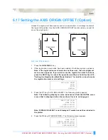
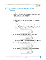
Load a medium with a pre-printed image.
2
Specify Off for the registration mark mode (see Section 6.12, “Setting the
Registration Mark Mode (Option)”.
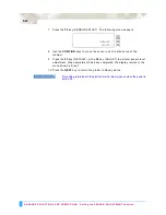
3
Select 3POINT for the axis alignment method (see Section 6.22, “Selecting the
Axis Alignment Method”).
4
Press the
AXIS/R.M.S.
key. The following menu appears.
5
Use the
POSITION
keys to move the pen carriage to Axis Point 1. The
displayed X- and Y-coordinate values represent the current pen carriage
position as X- and Y-axis offsets from the current origin.
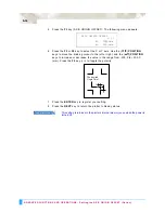
6
Press the
ENTER
key to register the setting. The following menu appears.
7
Use the
POSITION
keys to move the pen carriage to Axis Point 2.
8
Press the
ENTER
key to register the setting. The following menu appears.
9
Use the
POSITION
keys to move the pen carriage to Axis Point 3.
10 Press the
ENTER
key to register the setting. The following menu appears.
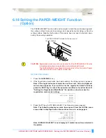
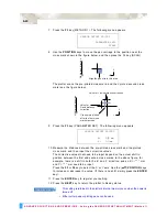
11 To perform distance correction, use the
POSITION
keys to input the corrective
value for the distance between points 1 and 2. The measured value for the
distance between points 1 and 2 is shown in the 3rd row. Set the actual
distance in the 4th row. Use the (
▲▼
)
POSITION
keys to change the value.
Press the
ENTER
key to register your setting. If the value does not need to be
corrected, simply press the
ENTER
key. The following menu appears.
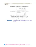
12 To perform distance correction, use the
POSITION
keys to input the corrective
value for the distance between points 1 and 3. The measured value for the
distance between points 1 and 3 is shown in the 3rd row. Set the actual
distance in the 4th row. Use the (
▲▼
)
POSITION
keys to change the value.
Press the
ENTER
key to register your setting. If the value does not need to be
corrected, simply press the
ENTER
key. The following menu appears.
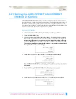
13 Use the
POSITION
keys to move the pen carriage to the Axis Origin Point.
AXIS POINT 1
X=
0 mm
Y=
0 mm
AXIS POINT 2
X=
0 mm
Y=
0 mm
AXIS POINT 3
X=
0 mm
Y=
0 mm
DISTANCE
POINT 1-2
00099.8 mm
OK?
00100.0 mm
DISTANCE
POINT 1-3
00101.1 mm
OK?
00100.0 mm
AXIS ORIGIN POINT
X=
0 mm
Y=
0 mm
Содержание Q100
Страница 34: ...Cutter Blades and Cutter Pens Adjusting the Blade Length 2 6 ...
Страница 64: ...Pen Setting Conditions Adjusting the Blade Length 4 12 ...
Страница 140: ...ADVANCED FUNCTIONS AND OPERATIONS Selecting the Type of Perforated Line 6 62 ...
Страница 148: ...OPTIONS Pen Offset for 2 pen models only 7 8 ...
Страница 174: ...INTERFACES COMMAND Settings 10 8 ...


