


Figure G-1 Web Interface PPS and GPS Qualifier Option Selections
Figure G-2 Top of Hour Counters
Figure G-3 Sub-Second Counter Behavior
Figure G-4 Minutes and Seconds Counter Behavior
Figure H-1 Direction of Laser Firing
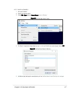
Figure H-2 Configuration Screen - Phase Lock
Figure H-3 Right and Left Sensor Phase Offset
Figure H-4 Fore and Aft Sensor Phase Offset
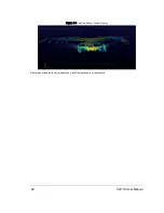
Figure H-5 Sensor Data Shadows
Figure J-1 Sensor Network Settings
Figure J-2 Single Sensor Broadcasting on a Simple Network
Figure J-3 Multiple Sensors - Improper Network Setup
Figure J-4 Multiple Sensors - Proper Network Setup
14
VLP-16 User Manual
Содержание VLP-16
Страница 1: ...VLP 16 User Manual 63 9243 Rev D ...
Страница 64: ...Figure 9 9 Single Return Mode Timing Offsets in µs 64 VLP 16 User Manual ...
Страница 86: ...http 192 168 1 201 cgi setting laser on 204 OK Sensor laser is On motor rpm is 301 86 VLP 16 User Manual ...
Страница 106: ...C 6 Puck Hi Res Optical Drawing Figure C 6 Puck Hi Res OpticalDrawing 86 0129 Rev A 106 VLP 16 User Manual ...
Страница 109: ...D 1 Interface Box Wiring Diagram Figure D 1 Interface Box Wiring Diagram 86 0107A Appendix D Wiring Diagrams 109 ...
Страница 110: ...D 2 Interface Box Schematic Figure D 2 Interface Box Schematic 69 8230A 110 VLP 16 User Manual ...