

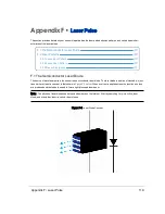
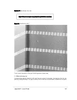

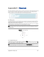


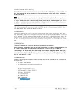


Figure H-3 Right and Left Sensor Phase Offset
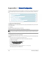
When sensors are placed on the roof in the fore and aft positions, the phase offsets are set to 180° and 0° as shown in
.
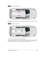
Figure H-4 Fore and Aft Sensor Phase Offset
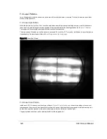
In both scenarios the two sensors create data shadows behind each other.
To avoid any spurious data due to blockage or reflections from the opposing sensor, the user should ignore any data in the
shadowed azimuth ranges as shown in
. To do that, you need to know the diameter of the
Sensor Specifications on page 91
) and distance between the sensor centers.
Appendix H • Phase Lock
129
Содержание VLP-16
Страница 1: ...VLP 16 User Manual 63 9243 Rev D ...
Страница 64: ...Figure 9 9 Single Return Mode Timing Offsets in µs 64 VLP 16 User Manual ...
Страница 86: ...http 192 168 1 201 cgi setting laser on 204 OK Sensor laser is On motor rpm is 301 86 VLP 16 User Manual ...
Страница 106: ...C 6 Puck Hi Res Optical Drawing Figure C 6 Puck Hi Res OpticalDrawing 86 0129 Rev A 106 VLP 16 User Manual ...
Страница 109: ...D 1 Interface Box Wiring Diagram Figure D 1 Interface Box Wiring Diagram 86 0107A Appendix D Wiring Diagrams 109 ...
Страница 110: ...D 2 Interface Box Schematic Figure D 2 Interface Box Schematic 69 8230A 110 VLP 16 User Manual ...