


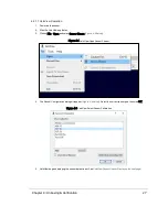

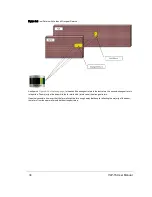

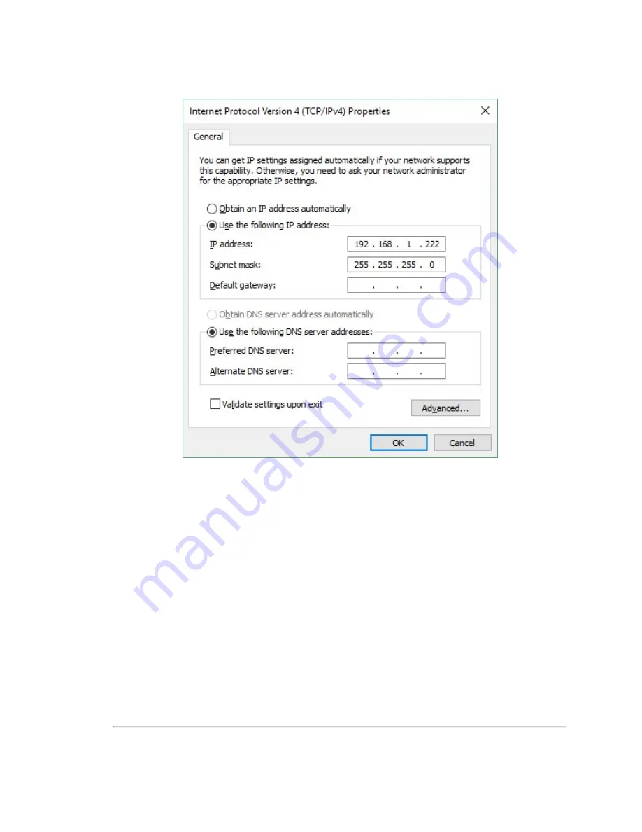
Figure 4-1 Sensor Network Settings
7. Click OK. Gateway and DNS are not necessary when testing in isolation.
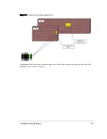
In some cases it may be necessary to disable the computer’s firewall or configure it to allow UDP I/O on that Ethernet inter-
face. How to do this is not covered here as the process varies widely.
4.2.2 Access Sensor’s Web Interface
Now the computer is ready to connect to the sensor.
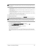
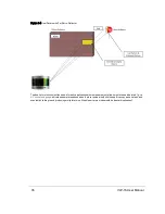
1. Plug the Ethernet cable into the computer and then plug its other end into the Ethernet port on the sensor’s Inter-
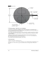
shows the Interface Box, its external ports, internal sensor terminal, and
fuse.
24
VLP-16 User Manual
Содержание VLP-16
Страница 1: ...VLP 16 User Manual 63 9243 Rev D ...
Страница 64: ...Figure 9 9 Single Return Mode Timing Offsets in µs 64 VLP 16 User Manual ...
Страница 86: ...http 192 168 1 201 cgi setting laser on 204 OK Sensor laser is On motor rpm is 301 86 VLP 16 User Manual ...
Страница 106: ...C 6 Puck Hi Res Optical Drawing Figure C 6 Puck Hi Res OpticalDrawing 86 0129 Rev A 106 VLP 16 User Manual ...
Страница 109: ...D 1 Interface Box Wiring Diagram Figure D 1 Interface Box Wiring Diagram 86 0107A Appendix D Wiring Diagrams 109 ...
Страница 110: ...D 2 Interface Box Schematic Figure D 2 Interface Box Schematic 69 8230A 110 VLP 16 User Manual ...