


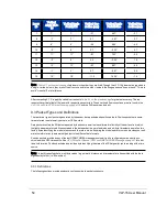


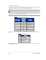


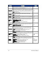


9.3.3 Position Packet Structure
The position packet provides an echo of the NMEA sentence received from an external time source as well as the Pulse
Per Second status and a time stamp representing when the position packet was assembled.
The position packet is a 554 byte UDP packet received on port 8308. The structure of the position packet is given in
Note: You may notice the timestamps in the position packets are occasionally out of order with respect to the data pack-
ets. This is normal as the delivery of data packets is the sensor's highest priority, and a position packet may get deferred
momentarily in favor of transmitting a data packet. The ratio of data packets to position packets is about 14 to 1. See
for details on the GPRMC message.
Number of Bytes
Byte Offset from
beginning of
packet (hex)
Description
42
0x0000
UDP header
198
0x002A
unused (null bytes)
4
0x00F0
Timestamp (µs)
1
0x00F4
Pulse Per Second status
3
0x00F5
unused
variable length
0x00F8
NMEA GPRMC sentence
Table 9-3 Position Packet Structure Field Offsets
Payload length is 512 bytes. The GPRMC sentence is terminated with CR/LF and padded to end of payload with null
bytes.
Value
Description
0
No PPS detected
1
Synchronizing to PPS
2
PPS Locked
3
Error
Table 9-4 PPS Status Byte Values
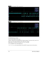
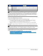
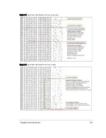
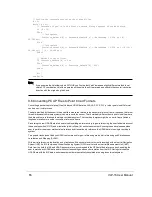
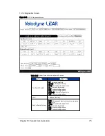
A position packet is shown in the figure below. Packet offsets are on the left, raw data bytes in hex are in the center, and the
ASCII interpretation is on the right.
60
VLP-16 User Manual
Содержание VLP-16
Страница 1: ...VLP 16 User Manual 63 9243 Rev D ...
Страница 64: ...Figure 9 9 Single Return Mode Timing Offsets in µs 64 VLP 16 User Manual ...
Страница 86: ...http 192 168 1 201 cgi setting laser on 204 OK Sensor laser is On motor rpm is 301 86 VLP 16 User Manual ...
Страница 106: ...C 6 Puck Hi Res Optical Drawing Figure C 6 Puck Hi Res OpticalDrawing 86 0129 Rev A 106 VLP 16 User Manual ...
Страница 109: ...D 1 Interface Box Wiring Diagram Figure D 1 Interface Box Wiring Diagram 86 0107A Appendix D Wiring Diagrams 109 ...
Страница 110: ...D 2 Interface Box Schematic Figure D 2 Interface Box Schematic 69 8230A 110 VLP 16 User Manual ...