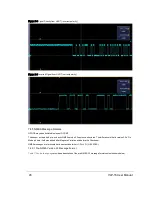


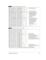


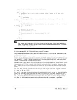


The packet data structure for Single Return Mode is shown in
. The packet data structure for Dual Return
.
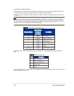
There are several key differences between the packet structures.
First, in Dual Return Mode the sensor sends a pair of data blocks for each azimuth angle firing. The odd numbered blocks
(1, 3, ..., 9, 11) contain either the strongest or second-strongest return and the even numbered blocks (0, 2, ..., 8, 10) con-
tain the last return.
If the strongest return is also the last return, then the second-strongest return is provided. If only one return was detected,
the data will be identical in the even|odd block pairs (0|1, 2|3, 4|5, 6|7, 8|9, 10|11).
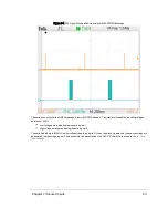
Figure 9-2 VLP-16 Single Return Mode Data Structure
Chapter 9 • Sensor Data
57
Содержание VLP-16
Страница 1: ...VLP 16 User Manual 63 9243 Rev D ...
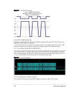
Страница 64: ...Figure 9 9 Single Return Mode Timing Offsets in µs 64 VLP 16 User Manual ...
Страница 86: ...http 192 168 1 201 cgi setting laser on 204 OK Sensor laser is On motor rpm is 301 86 VLP 16 User Manual ...
Страница 106: ...C 6 Puck Hi Res Optical Drawing Figure C 6 Puck Hi Res OpticalDrawing 86 0129 Rev A 106 VLP 16 User Manual ...
Страница 109: ...D 1 Interface Box Wiring Diagram Figure D 1 Interface Box Wiring Diagram 86 0107A Appendix D Wiring Diagrams 109 ...
Страница 110: ...D 2 Interface Box Schematic Figure D 2 Interface Box Schematic 69 8230A 110 VLP 16 User Manual ...