


Chapter 2 •
VLP-16 Overview
This chapter provides basic information on the sensor's hardware and software components.
2.4 Data Interpretation Requirements
2.1 Overview
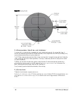
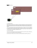
The VLP-16 sensor uses an array of 16 infra-red (IR) lasers paired with IR detectors to measure distances to objects. The
device is mounted securely within a compact, weather-resistant housing. The array of laser/detector pairs spins rapidly
within its fixed housing to scan the surrounding environment, firing each laser approximately 18,000 times per second,
providing, in real-time, a rich set of 3D point data.
Advanced digital signal processing and waveform analysis provide highly accurate long-range sensing, as well as cal-
ibrated reflectivity data, enabling easy detection of retro-reflectors like street-signs, license plates, and lane markings.
Combining 16 laser/detector pairs into one VLP-16 sensor and pulsing each at 18.08 kHz enables measurements of up to
300,000 data points per second -- or double that in dual return mode.
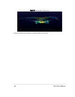
Figure 2-1 Example 3D Sensing System
18
VLP-16 User Manual
Содержание VLP-16
Страница 1: ...VLP 16 User Manual 63 9243 Rev D ...
Страница 64: ...Figure 9 9 Single Return Mode Timing Offsets in µs 64 VLP 16 User Manual ...
Страница 86: ...http 192 168 1 201 cgi setting laser on 204 OK Sensor laser is On motor rpm is 301 86 VLP 16 User Manual ...
Страница 106: ...C 6 Puck Hi Res Optical Drawing Figure C 6 Puck Hi Res OpticalDrawing 86 0129 Rev A 106 VLP 16 User Manual ...
Страница 109: ...D 1 Interface Box Wiring Diagram Figure D 1 Interface Box Wiring Diagram 86 0107A Appendix D Wiring Diagrams 109 ...
Страница 110: ...D 2 Interface Box Schematic Figure D 2 Interface Box Schematic 69 8230A 110 VLP 16 User Manual ...