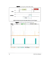
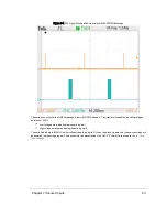
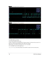


UTC synchronization requires a user-supplied GPS/INS receiver generating a synchronizing Pulse Per Second (PPS) sig-
nal and an NMEA GPRMC message. The GPRMC message provides minutes and seconds in UTC. Upon syn-
chronization, the sensor reads the minutes and seconds from the GPRMC message and uses the information to set the
sensor’s time stamp to the number of microseconds past the hour, per UTC.
Note: A full description of electrical and timing requirements can be found in
GPS, Pulse Per Second (PPS) and NMEA
. A full description of timing options can be found in
Time Synchronization on page 123
.
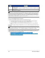
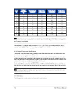
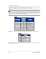
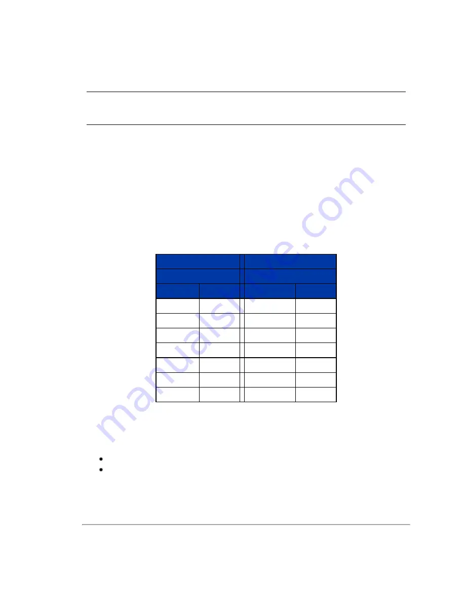
9.3.1.7 Factory Bytes
Beginning with firmware release 3.0.29.0, every data packet includes a pair of bytes called the Factory Bytes. Their values
indicate how azimuths and data points are organized in the packet. Their packet locations, values, and meanings are spe-
cified in
The Return Mode byte indicates how the packet’s azimuth and data points are organized. See
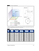
Every sensor model line has its lasers arrayed vertically at slightly different angles. Use the Product ID byte to identify the
correct set of vertical (or elevation) angles. Product IDs are not unique and may be shared by different sensors. For
example, per
, the VLP-16 and Puck LITE share the same elevation angles. Hence, the two products
share the same Product ID. Conversely, the Puck Hi-Res has a different Product ID since it has a different set of elevation
angles.
Return Mode
Product ID
Offset in packet: 0x04DE
Offset in packet: 0x04DF
Mode
Value
Product Model
Value
Strongest
0x37 (55)
HDL-32E
0x21 (33)
Last Return
0x38 (56)
VLP-16
0x22 (34)
Dual Return
0x39 (57)
Puck LITE
0x22 (34)
--
--
Puck Hi-Res
0x24 (36)
--
--
VLP-32C
0x28 (40)
--
--
Velarray
0x31 (49)
--
--
VLS-128
0x63 (99)
Table 9-2 Factory Byte Values
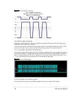
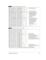
9.3.2 Data Packet Structure
A data packet is 1248 bytes long and sent via a UDP packet on port 2368. The data packet is comprised of 42 bytes of pro-
tocol header, twelve Data Blocks, a four-byte timestamp, and two factory bytes.
There are two formats for the data packet:
Single Return Mode (either Strongest or Last)
Dual Return Mode
for an illustration of what Strongest, Last, and Dual mean in this context.
56
VLP-16 User Manual
Содержание VLP-16
Страница 1: ...VLP 16 User Manual 63 9243 Rev D ...
Страница 64: ...Figure 9 9 Single Return Mode Timing Offsets in µs 64 VLP 16 User Manual ...
Страница 86: ...http 192 168 1 201 cgi setting laser on 204 OK Sensor laser is On motor rpm is 301 86 VLP 16 User Manual ...
Страница 106: ...C 6 Puck Hi Res Optical Drawing Figure C 6 Puck Hi Res OpticalDrawing 86 0129 Rev A 106 VLP 16 User Manual ...
Страница 109: ...D 1 Interface Box Wiring Diagram Figure D 1 Interface Box Wiring Diagram 86 0107A Appendix D Wiring Diagrams 109 ...
Страница 110: ...D 2 Interface Box Schematic Figure D 2 Interface Box Schematic 69 8230A 110 VLP 16 User Manual ...