

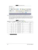


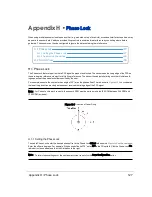


The current phase lock status (On/Off) and phase lock offset can be viewed on the Web Interface (red box). The current
phase lock offset is presented in degrees. The accuracy of the offset is ±5° (subject to change).
Figure H-2 Configuration Screen - Phase Lock
H.1.2 Application Scenarios
When setting the phase lock offset for two or more sensors, Velodyne recommends the sensors be configured to fire at
each other. This is the optimal configuration for minimizing interference because the location of the interference is under
user control.
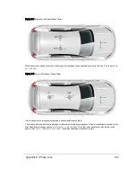
shows two sensors mounted on a vehicle. The sensor mounted on the car’s left side has its
phase lock offset set to 90°, and the phase lock offset of the sensor mounted on the right side of the vehicle is set to 270°, as
shown by the red arrows.
128
VLP-16 User Manual
Содержание VLP-16
Страница 1: ...VLP 16 User Manual 63 9243 Rev D ...
Страница 64: ...Figure 9 9 Single Return Mode Timing Offsets in µs 64 VLP 16 User Manual ...
Страница 86: ...http 192 168 1 201 cgi setting laser on 204 OK Sensor laser is On motor rpm is 301 86 VLP 16 User Manual ...
Страница 106: ...C 6 Puck Hi Res Optical Drawing Figure C 6 Puck Hi Res OpticalDrawing 86 0129 Rev A 106 VLP 16 User Manual ...
Страница 109: ...D 1 Interface Box Wiring Diagram Figure D 1 Interface Box Wiring Diagram 86 0107A Appendix D Wiring Diagrams 109 ...
Страница 110: ...D 2 Interface Box Schematic Figure D 2 Interface Box Schematic 69 8230A 110 VLP 16 User Manual ...