


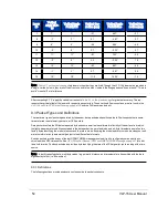


Laser
ID
Vertical
Angle VLP-
16
Vertical Angle
Puck LITE
Vertical Cor-
rection (mm)
Vertical Angle
Puck Hi-Res
Vertical Cor-
rection (mm)
7
7°
7°
-5.1
4.67°
-3.7
8
-7°
-7°
5.1
-4.67°
3.7
9
9°
9°
-6.6
6.00°
-4.6
10
-5°
-5°
3.7
-3.33°
2.7
11
11°
11°
-8.1
7.33°
-5.5
12
-3°
-3°
2.2
-2.00°
1.8
13
13°
13°
-9.7
8.67°
-6.5
14
-1°
-1°
0.7
-0.67°
0.9
15
15°
15°
-11.2
10.00°
-7.4
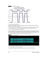
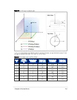
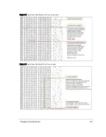
Table 9-1 on the previous page
lists lasers in the order they are fired. Though the VLP-16's lasers are organized in
a single, vertical column, they are not fired from one end to the other. Instead, the firing sequence "hops around." This is to
avoid "cross-talk" or interference.
After computing X,Y,Z, apply the vertical correction in
Table 9-1 on the previous page
for greatest accuracy. This rep-
resents the vertical offset of the laser with respect to sensor origin. These vertical offset corrections are also found in the
VLP-16 and Puck LITE Optical Drawing on page 103
and the Hi-Res version below it.
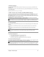
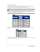
9.3 Packet Types and Definitions
There are two types of packets generated by the sensor: data packets and position packets. Position packets are some-
times referred to as telemetry packets, or GPS packets.
Data packets contain the 3D data measured by the sensor as well as the calibrated reflectivity of the surface from which
the light pulse was returned. Also contained in the data packet is a set of azimuths and a 4-byte timestamp, as well as two
factory bytes identifying the model of sensor and the return mode. Knowing the model and return mode provides your soft-
ware the information to automatically adjust to the different data formats.
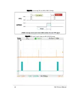
Position packets provide a copy of the last GPRMC NMEA message received if you've configured your sensor to syn-
chronize with a GPS time source. See
GPS, Pulse Per Second (PPS) and NMEA GPRMC Message on page 41
tional information. Position packets also provide a byte identifying the state of the PPS signal for synchronizing with a time
source.
Note: In both types of packets, multi-byte values (e.g. azimuth, distance, and timestamp) are transmitted with the least
significant byte first (i.e. little-endian).
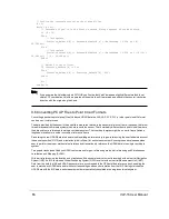
9.3.1 Definitions
The following sections provide explanations of sensor data packet constructs.
54
VLP-16 User Manual
Содержание VLP-16
Страница 1: ...VLP 16 User Manual 63 9243 Rev D ...
Страница 64: ...Figure 9 9 Single Return Mode Timing Offsets in µs 64 VLP 16 User Manual ...
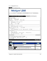
Страница 86: ...http 192 168 1 201 cgi setting laser on 204 OK Sensor laser is On motor rpm is 301 86 VLP 16 User Manual ...
Страница 106: ...C 6 Puck Hi Res Optical Drawing Figure C 6 Puck Hi Res OpticalDrawing 86 0129 Rev A 106 VLP 16 User Manual ...
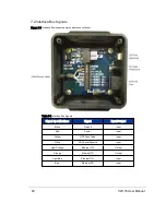
Страница 109: ...D 1 Interface Box Wiring Diagram Figure D 1 Interface Box Wiring Diagram 86 0107A Appendix D Wiring Diagrams 109 ...
Страница 110: ...D 2 Interface Box Schematic Figure D 2 Interface Box Schematic 69 8230A 110 VLP 16 User Manual ...