


F.2 Laser Patterns
Laser firings produced by the sensor can be viewed with an infrared viewer or camera. Photos in this section were taken
with an infrared camera.
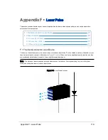
F.2.1 Laser Spot Pattern
While the terms laser “spot” and “dot” are often used when describing a laser pulse hitting a target, in reality the sensor’s
laser “spot” is a small rectangular area comprised of three smaller bars or bands of light as shown in
.
The long axis of the rectangle coincides with the direction of the laser scan.
The dimensions of this laser spot at the sensor’s ring lens is 9.5 mm tall by 12.7 mm wide - but it doesn’t remain that size as
it speeds away. Read more about that in
Beam Divergence on the facing page
Figure F-2 Laser Spot Shape
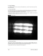
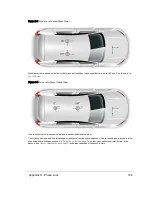
F.2.2 Laser Scan Pattern
Inside each VLP-16 sensor is a vertical array of lasers.
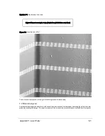
shows three adjacent, concurrent,
laser scans on the corner of a wall about 3 meters from the sensor. Each laser scan is composed of multiple laser spots or
pulses. Each spot is composed of three short closely-spaced horizontal bars or bands of light.
The gap between scan lines can be calculated with the following equation:
120
VLP-16 User Manual
Содержание VLP-16
Страница 1: ...VLP 16 User Manual 63 9243 Rev D ...
Страница 64: ...Figure 9 9 Single Return Mode Timing Offsets in µs 64 VLP 16 User Manual ...
Страница 86: ...http 192 168 1 201 cgi setting laser on 204 OK Sensor laser is On motor rpm is 301 86 VLP 16 User Manual ...
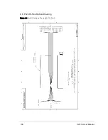
Страница 106: ...C 6 Puck Hi Res Optical Drawing Figure C 6 Puck Hi Res OpticalDrawing 86 0129 Rev A 106 VLP 16 User Manual ...
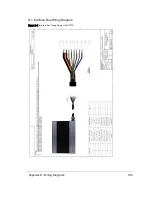
Страница 109: ...D 1 Interface Box Wiring Diagram Figure D 1 Interface Box Wiring Diagram 86 0107A Appendix D Wiring Diagrams 109 ...
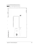
Страница 110: ...D 2 Interface Box Schematic Figure D 2 Interface Box Schematic 69 8230A 110 VLP 16 User Manual ...