


Appendix J •
Network Configuration
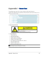
Your sensor generates lots of data which it transmits via Ethernet. This section covers various aspects of this interface and
how to connect and configure it. It also touches on the situation where you have more than one sensor on the same net-
work.
J.1 Ethernet and Network Setup
J.1.2 Establishing Communication via Ethernet
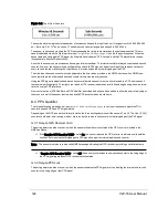
J.2.2 Single Sensor Transmitting to a Broadcast Address
J.2.3 Multiple Sensors in the Same Network
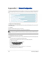
J.1 Ethernet and Network Setup
The RJ45 Ethernet connector on the Interface Box connects to any standard 100 Mbps Ethernet NIC or switch with MDI
or AUTO MDIX capability.
J.1.1 Defaults
Each sensor’s IP address is set at the factory to 192.168.1.201.
By default, the sensor sends UDP data packets to broadcast address 255.255.255.255.
Note: Each sensor has a unique MAC Address and Serial Number set at the factory by Velodyne LiDAR that cannot be
changed.
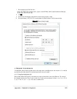
J.1.2 Establishing Communication via Ethernet
The instructions below are for Windows computers. For linux or Macintosh computers, perform equivalent steps (not spe-
cified here).
1. Connect the computer to the Interface Box with an Ethernet cable.
Velodyne recommends disabling WiFi on your computer to avoid possible network conflicts.
2. Provide power to the sensor.
3. Open your computer’s Network/Ethernet settings page.
4. Select Internet Protocol Version 4 (TCP/IPv4).
5. Select the Use the following IP address: function.
The sensor requires a static IP address.
6. Enter the following IP address: 192.168.1.XXX. See
.
“XXX” can be any number from 2 to 254 except 201.
134
VLP-16 User Manual
Содержание VLP-16
Страница 1: ...VLP 16 User Manual 63 9243 Rev D ...
Страница 64: ...Figure 9 9 Single Return Mode Timing Offsets in µs 64 VLP 16 User Manual ...
Страница 86: ...http 192 168 1 201 cgi setting laser on 204 OK Sensor laser is On motor rpm is 301 86 VLP 16 User Manual ...
Страница 106: ...C 6 Puck Hi Res Optical Drawing Figure C 6 Puck Hi Res OpticalDrawing 86 0129 Rev A 106 VLP 16 User Manual ...
Страница 109: ...D 1 Interface Box Wiring Diagram Figure D 1 Interface Box Wiring Diagram 86 0107A Appendix D Wiring Diagrams 109 ...
Страница 110: ...D 2 Interface Box Schematic Figure D 2 Interface Box Schematic 69 8230A 110 VLP 16 User Manual ...