


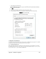


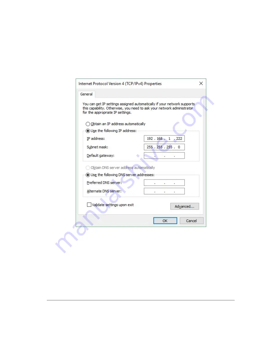
7. Enter the subnet mask: 255.255.255.0
When using a Windows OS based computer, you can press the TAB key and the subnet mask automatically pop-
ulates with the 255.255.255.0 value.
8. Click OK.
9. We recommend disabling any firewall software the computer may have running.
10. Point your browser to 192.168.1.201 to access the sensor’s Web Interface to confirm communication.
Figure J-1 Sensor Network Settings
J.2 Network Considerations
Your application network topology may be simple, with a single sensor transmitting data on a basic network. Or, it could be
complicated, with multiple sensors. This section presents certain topics to consider.
J.2.1 Throughput Requirements
When actively sensing its environment, your sensor produces a lot of data which it transmits via Ethernet. The volume of
data depends partly on which Return Type (or mode) it’s in. Details on return modes can be found in
. See
for return mode data rates.
Appendix J • Network Configuration
135
Содержание VLP-16
Страница 1: ...VLP 16 User Manual 63 9243 Rev D ...
Страница 64: ...Figure 9 9 Single Return Mode Timing Offsets in µs 64 VLP 16 User Manual ...
Страница 86: ...http 192 168 1 201 cgi setting laser on 204 OK Sensor laser is On motor rpm is 301 86 VLP 16 User Manual ...
Страница 106: ...C 6 Puck Hi Res Optical Drawing Figure C 6 Puck Hi Res OpticalDrawing 86 0129 Rev A 106 VLP 16 User Manual ...
Страница 109: ...D 1 Interface Box Wiring Diagram Figure D 1 Interface Box Wiring Diagram 86 0107A Appendix D Wiring Diagrams 109 ...
Страница 110: ...D 2 Interface Box Schematic Figure D 2 Interface Box Schematic 69 8230A 110 VLP 16 User Manual ...