5.- SOFTWARE DESCRIPTION
- 55 -
5.4.2.- Transformer technical data
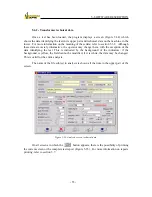
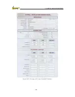
Once a test has been loaded, the program displays a screen (Figure 5-34) which
shows the data identifying the test in its upper part and technical data on the machine in the
lower. For more information on the meaning of these data, refer to section 5.3.2. Although
these data are merely informative, the operator may change them, with the exception of the
data identifying the test. This is indicated by the background of the indicators: if the
background is yellow, the field cannot be modified; if it is white, the data may be changed.
This is valid for the entire analysis.
The name of the file subject to analysis is shown all the time in the upper part of the
screen.
Figure 5-34: Analysis screen, technical data.
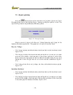
On all screens in which the
button appears, there is the possibility of printing
the current screen or the complete test report (Figure 5-35). For more information on reports
printing, refer to section 5.7.
Содержание UM2B
Страница 2: ......
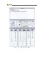
Страница 49: ...5 SOFTWARE DESCRIPTION 47 Figure 5 18 Warning message Figure 5 19 a Measurement Screen Recovery Voltage ...
Страница 67: ...5 SOFTWARE DESCRIPTION 65 Figure 5 46 a First page of the report Recovery Voltage ...
Страница 68: ...5 SOFTWARE DESCRIPTION 66 Figure 5 47 a Second page of report Recovery Voltage ...
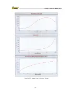
Страница 69: ...5 SOFTWARE DESCRIPTION 67 Figure 5 48 Third page of report Recovery Voltage ...
Страница 70: ...5 SOFTWARE DESCRIPTION 68 Figure 5 46 b First page of the report Insulation Resistance ...
Страница 71: ...5 SOFTWARE DESCRIPTION 69 Figure 5 47 b Second page of the report Insulation Resistance ...
Страница 87: ...8 TECHNICAL SUPPORT 85 Description of fault Materials returned on of of the year Table 8 1 ...
Страница 95: ...APPENDIX B CONTROL SOFTWARE 93 APPENDIX A CE CONFORMITY DECLARATION ...


