4.- PREPARATIONS BEFORE TO USE
- 24 -
- Safety check.
The equipment to be measured should be checked to ensure that it is duly
isolated from the external connection lines and completely discharged.
- Connection of high voltage cables to UM2B.
The high voltage cables should first be connected to the unit (8). Next,
choose measurement configuration to perform test. The phases of each
winding (high/low) will be put on short circuit. The phases may be
interconnected by means of bare copper wire if the distances are short and
there is no risk of short-circuiting to ground; otherwise, a proper insulating
cable should be used. Finally, connect positive / negative terminal according
to software indications.
Never remove high voltage connectors during test.
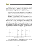
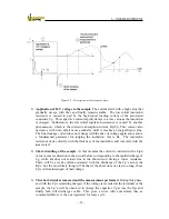
Figure 4-2: Configuration of the test.
V max.:
2000 V dc
I max.:
5 mA
Installation:
CAT II
For properly measuring, the cables must be completely stretched until the
measurement point without creases, or anyway, that these have a radius
not under 200 mm.
Содержание UM2B
Страница 2: ......
Страница 49: ...5 SOFTWARE DESCRIPTION 47 Figure 5 18 Warning message Figure 5 19 a Measurement Screen Recovery Voltage ...
Страница 67: ...5 SOFTWARE DESCRIPTION 65 Figure 5 46 a First page of the report Recovery Voltage ...
Страница 68: ...5 SOFTWARE DESCRIPTION 66 Figure 5 47 a Second page of report Recovery Voltage ...
Страница 69: ...5 SOFTWARE DESCRIPTION 67 Figure 5 48 Third page of report Recovery Voltage ...
Страница 70: ...5 SOFTWARE DESCRIPTION 68 Figure 5 46 b First page of the report Insulation Resistance ...
Страница 71: ...5 SOFTWARE DESCRIPTION 69 Figure 5 47 b Second page of the report Insulation Resistance ...
Страница 87: ...8 TECHNICAL SUPPORT 85 Description of fault Materials returned on of of the year Table 8 1 ...
Страница 95: ...APPENDIX B CONTROL SOFTWARE 93 APPENDIX A CE CONFORMITY DECLARATION ...

