4.- PREPARATIONS BEFORE TO USE
- 22 -
4.1.- Precautions in the area of installation
When this instrument is used to test high voltage machines, all the
habitual safety procedures and standards applicable to this type of
machines should be adhered to. Ensure in all cases that the
equipment being tested is completely discharged and grounded
before touching it.
For the safety of the equipment operators or any other worker in the area, as well as
for the integrity of the system itself and to ensure that the measurement results are valid, a
series of precautions should be taken at the test location. These may be summarized as
follows:
Check that the surrounding area is appropriate (without rain or dust storms) and that
it is within the temperature / humidity margins specified for the operation (see
chapter 9: Specifications).
Check that the system supply voltage is within the specific operating
limits (see chapter 9: Specifications) and that it is grounded. This ground
should match with that of the equipment being tested. In case of doubt,
the best thing is to run a thick plaited grounding cable from the system
supply to the equipment tested.
Check that the equipment to be tested is free from its operating voltage or any
remnant voltage (it is most advisable for the machine to have been in a previous short
circuit state before the test).
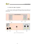
Position the measuring unit and the control computer close to the equipment being
tested, as shown in Figure 4-1.
Isolate the test area by means of the necessary mechanical elements, as homologated
by the safety department of each company, such as cones, fencing, safety tapes of
different colors located at waist height, etc.
Содержание UM2B
Страница 2: ......
Страница 49: ...5 SOFTWARE DESCRIPTION 47 Figure 5 18 Warning message Figure 5 19 a Measurement Screen Recovery Voltage ...
Страница 67: ...5 SOFTWARE DESCRIPTION 65 Figure 5 46 a First page of the report Recovery Voltage ...
Страница 68: ...5 SOFTWARE DESCRIPTION 66 Figure 5 47 a Second page of report Recovery Voltage ...
Страница 69: ...5 SOFTWARE DESCRIPTION 67 Figure 5 48 Third page of report Recovery Voltage ...
Страница 70: ...5 SOFTWARE DESCRIPTION 68 Figure 5 46 b First page of the report Insulation Resistance ...
Страница 71: ...5 SOFTWARE DESCRIPTION 69 Figure 5 47 b Second page of the report Insulation Resistance ...
Страница 87: ...8 TECHNICAL SUPPORT 85 Description of fault Materials returned on of of the year Table 8 1 ...
Страница 95: ...APPENDIX B CONTROL SOFTWARE 93 APPENDIX A CE CONFORMITY DECLARATION ...

