13
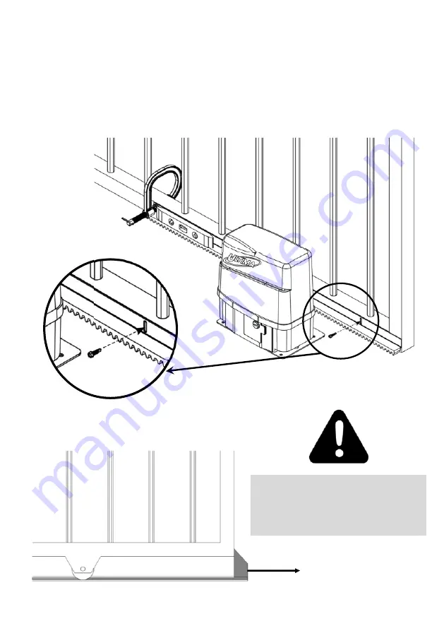
1. Rest the rack on the pinion with the end of the rack and the end of the gate aligned. Having the gate slightly
open will allow access to the first slot on the rack.
2. Clamp the opposite end of the rack to the gate.
3. Using a spirit level, ensure the rack is level.
4. Fasten the rack to the gate with the self drilling TEK screws through the slots in the rack.
5. To aGach addi2onal rack, slide the gate open and repeat the above procedures.
6. ALer the rack has been aGached, use the Height Adjustment Nuts on the founda2on plate for fine adjust-
ment.
Drill the TEK Screws
through the available
slots.
DO NOT automate a gate without end stops
welded in posi2on on both ends of the gate rail.
These are used during the programming of the
limits and are also required for safety reasons.
“End Stop”
welded in posi&on
……..con2nued
Содержание HT18/36
Страница 6: ...6 TRITEK CONTROLLER SPECIFICATIONS Con2nues...
Страница 20: ...20 RECEIVER SAFETY BEAM B RECEIVER SAFETY BEAM A MAX LOAD 300mA TWO SETS OF SAFETY BEAMS RELAY OUTPUT...
Страница 21: ...21 RADIO RECEIVER LOOP DETECTOR MAX LOAD 300mA EXTERNAL RADIO RECEIVER LOOP DETECTOR...
Страница 22: ...22 RECEIVER SAFETY BEAM RECEIVER SAFETY BEAM CLOSING SAFETY BEAM RELAY OUTPUT CLOSING SAFETY BEAM FET OUTPUT...
Страница 23: ...23 RECEIVER SAFETY BEAM RECEIVER SAFETY BEAM OPENING SAFETY BEAM FET OUTPUT OPENING SAFETY BEAM RELAY OUTPUT...
Страница 26: ...26 ELECTRIC LOCK 3A MAX MAGNETIC LOCK 500mA max 12V 250mA max 24V ELECTRIC LOCK MAGNETIC LOCK...
Страница 51: ...51 NOTES...


