


your position is our focus
GND
RF_IN
GND
AADET_N/NC
15
16
17
18
19
28
27
26
25
24
23
22
21
20
14
13
12
11
10
1
2
3
4
5
6
7
8
9
VCC
TxD2
RxD2
RESET_N
VBAT
GND
RxD1
TxD1
BOOT_INT
GND
Vcc
Micro
cessor
Pro
(serial)
Passive Antenna
VCC_RF
V_ANT/NC
GPSMO
USB_DP
VDDUSB
USB_D
TIMEPULSE
EXTINT0
GND
VDDIO
DE5
M
VDD18OUT
LEA-
LEA-4S
GPSMODE2/
GPSMODE7
1)
4A / LEA-4M/
GPSMODE6
Backup
Battery
+
Micro
Processor
(USB)
1) USB selfpowered s
g
(optional)
ettin
USB port
GND
RF_IN
GND
ET_N
AAD
15
16
17
18
19
28
27
26
25
24
23
22
21
20
14
13
12
11
10
1
2
3
4
5
6
7
8
9
TxD1
RESET_N
BOOT_INT
GND
VCC
RxD1
MISO
MOSI
VBAT
GND
Vcc
Micro
Processor
(serial)
Passive Antenna
VCC_RF
V_ANT
EXTINT1/ P13
VDD18OUT
USB_DP
USB_DM
GND
VDDUSB
VDDIO
TIMEPULSE
EXTINT0/ P9
LEA-4P/ LEA-4H/
LEA-4T
PCS2_N/ P12
PCS0_N/ SS_N/ P26
SCK/ P23
Backup
Battery
+
Micro
Processor
(USB)
USB port (optional)
GPSMODE23
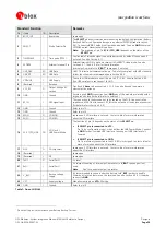
Figure 37: Passive Antenna Design
ceivers
for LEA-4x Re
Function
PIN
(
LEA)
I/O
Description
Remarks
Power
VDDIO
5
I
Supply
voltage
for
digital
I/O
pins
pins
(e.g.
serial
ports,
TIMEPULSE
).
Must
be
eting
datasheet
Power
Supply
for
the
digital
I/O
connected
to
VDD18OUT
,
VCC
or
other
voltage
source
me
specification.
ever leave open!
N
VCC
6
I
Supply
Voltage
50mVpp
Max
allowed
ripple
on
VCC
=
GND
7,
13-
15,
17
I
Ground
all
GND
pins
of
the
module,
preferably
with
Assure
a
good
GND
connection
to
a
large
ground
plane
(for
details
refer
to
Section 3.6.4
)
VDD18OUT
8
O
1.8V
supply
output
1.8V
output
voltage
reference.
Leave
open
if
not
used.
VBAT
11
I
Backup
voltage
supply
p
battery
to
V_BAT
in
order
to
enable
on
the
receivers.
Otherwise
connect
to
GND
.
See
It’s
recommended
to
connect
a
backu
Warm
and
Hot
Start
features
also
Section 4.2.2
.
VDD_USB
24
I
USB
Power
Supply
To
use
the
USB
interface
connect
this
pin
to
3.0
–
3.6V.
See
also
Section 4.4.2
If
no
USB
serial
port
used
connect
to
GND.
Antenna
RF_IN
16
I
from
antenna
e
a
controlled
RF_IN
to
the
antenna
or
the
antenna
tion 3.6.5)
GPS
signal
input
The
connection
to
the
antenna
has
to
be
routed
on
the
PCB.
Us
impedance
of
50
Ohm
to
connect
connector
(for
details
refer
to
Sec
Don’t
supply
DC
through
this
pin.
Use
V_ANT
pin
to
supply
power.
VCC_RF
18
Output
Voltage
RF
section
of
the
Antenna
must
not
exceed
the
the
module
(see
also
4.3.3
).
O
Can
be
used
to
power
an
external
active
antenna
(
VCC_RF
connected
to
V_ANT
).
The
max
power
consumption
datasheet
specification
of
Leave
open
if
not
used.
I
Antenna
Bias
voltage
GND
If
Antenna
input
to
the
Antenna
Bias
Voltage
or
VCC_RF
for
short
circuit
protection
or
use
the
antenna
supervisor
circuitry
(see
4.3.3.2
).
This
pin
is
not
available
on
LEA-4M
(see
section
3.6.6
for
more
information).
Connect
to
if
Passive
Antenna
is
used.
an
active
is
used,
add
a
10R
resistor
(see
4.3.3.2
)
in
front
of
V_ANT
V_ANT
19
AADET_N
20
I
Active
Antenna
Detect
Input
pin
for
optional
antenna
supervisor
circuitry
(
see 4.3.3.2
).
Leave
open
if
not
used.
This
pin
is
not
available
on
LEA-4M
(see
section
3.6.6
for
more
information).
GPS
Modules
-
System
Integration
Manual
(SIM)
(incl.
Reference
Design)
Design-In
GPS.G4-MS4-05007-A1
Page 45


