


Another
benefit
is
the
use
of
GPS
integrity
information.
In
that
way
SBAS
Control
stations
can
‘disable’
usage
of
GPS
satellites
in
case
of
major
GPS
satellite
problems
within
6
seconds
time
to
alarm.
The
ANTARIS
®
4
GPS
•
RTCA/DO-229C
(MOPS).
Available
from
www.rtca.org
Technology
will
only
use
satellites,
for
which
integrity
information
is
available,
if
integrity
monitoring
is
enabled.
For
more
information
on
SBAS
and
associated
services
please
refer
to
•
gps.faa.gov
for
information
on
WAAS
and
the
NSTB
•
www.esa.int
for
information
on
EGNOS
and
the
ESTB
•
www.essp.be
for
information
about
European
Satellite
Services
Provider
EEIG
is
the
EGNOS
operations
manager.
SBAS GEO PRN Numbers
The
PRN
of
the
GEO’s
used
for
SBAS
are
in
a
range
from
120
to
150.
shows
the
SBAS
GEO’s
in
operation.
GEO
identification
Stationed
over
GPS
PRN
SBAS
Provider
INMARSAT
AOR-E
(Atlantic
Ocean
Region
East)
Eastern
Africa
120
EGNOS
INMARSAT
AOR-W
(Atlantic
Ocean
Region
West)
Western
Africa
122
WAAS
Artemis
Africa
(Congo)
124
EGNOS
INMARSAT
IOR-W
(III-F5)
(Indian
Ocean
Region
West)
Africa
(Congo)
126
EGNOS
MTSAT-1R
Pacific
129
MSAS
INMARSAT
IOR
(Indian
Ocean
Region)
Indian
Ocean
131
EGNOS
INMARSAT
POR
(Pacific
Ocean
Region)
Pacific
134
WAAS
PanAmSat
Galaxy
15
133
degrees
west
135
WAAS
MT AT-2
Pacific
(not
lau
S
nched
yet)
137
MSAS
Tele at
Anik
/
F1R
s
st
138
WAAS
107
degree
we
Table 2: PRN of GEO's used for SBAS
a
feature
to
make
GPS
more
accurate
and
reliable
in
urban
canyon
environments
and
during
e
to
measure
its
speed,
a
GPS
receiver,
a
turn
rate
sensor
(gyroscope)
and
a
speed
indicator
(odometer).
By
combining
the
information
of
all
sensors
a
position
can
be
determined
even
if
GPS
positioning
is
degraded
or
impossible
due
to
restricted
sky
view.
This
means
that
a
DR
enabled
receiver
continues
to
report
positions,
when
GPS
signals
are
blocked,
such
as
in
tunnels
or
in
heavy
urban
canyon
environments.
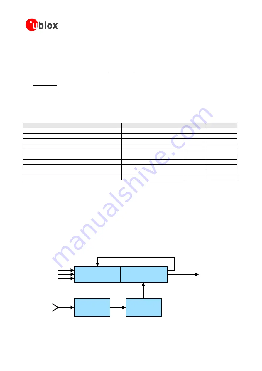
1.11 Dead Reckoning enabled GPS (DR)
Dead
reckoning
is
periods
of
GPS
outage.
It
uses
extra
sensors
(in
addition
to
GPS)
installed
in
the
vehicl
heading
and
direction
(forward,
backward).
Therefore
a
DR
enabled
Receiver
consists
of
GPS Kalman Filter
GPS
receiver
Dead Reckoning
Parameter
Enhanced Kalman Filter (EKF)
Position,
Speed,
Direction,
Time
Calibration
Turn
Rate
Speed
Forward/Backward
Signals
GPS
Position,
GPS
ata
GPS
D
Figure 27: Dead Reckoning Block diagram
GPS
Modules
-
System
Integration
Manual
(SIM)
(incl.
Reference
Design)
GPS
Fundamentals
GPS.G4-MS4-05007-A1
Page 32


