your position is our focus
4.7 Timing
4.7.1 TIMEPULSE
ANTARIS
®
4
GPS
receivers
provide
a
hardware-synchronized
TIMEPULSE
(Pin
29)
with
a
Time
Pulse Period
of
1
ms
to
60
s.
The
polarity
(rising
or
falling
edge)
and
the
pulse
duration
can
be
configured.
Use
the
UBX
proprietary
message
UBX
-
CFG
(Config)
-
TP
(Time
Pulse)
to
change
the
TIMEPULSE
settings.
The
UBX
-
TIM
(Time)
-
TP
(Timepulse)
message
provides
the
time
information
for
the
next
TIMEPULSE,
time
source
and
a
quantization
error.
Parameter
Description
Pulse Mode
‘falling
edge’
‘disabled’
TIMEPULSE
synchronization
on
the
falling
edge
TIMEPULSE
disabled
(output
signal
low)
‘rising
edge’
TIMEPULSE
synchronization
on
the
rising
edge
Pulse Period
e
TIM
Period
of
th
EPULSE
Pulse Length
the
Duration
of
TIMEPULSE
Pulse Frequency
The
pulse
frequency
is
calculated
from
the
pulse
period
(u-center
output
only)
Time Source
Selection
whether
the
Time
Pulse
is
GPS
time
or
UTC
time
synchronized
Cable Delay
the
iver
Signal
delay
in
cable
from
the
antenna
to
the
ANTARIS 4
GPS
Rece
®
User Delay
The
cable
delay
from
ignal
delay
of
any
user
application
ANTARIS
®
4
GPS
Receiver
to
the
user
device
plus
s
RF Group Delay
Delay
of
the
signal
in
the
ANTARIS
®
4
GPS
Receiver
RF
module
(hard
coded)
Table 40: TIMEPULSE Parameter description
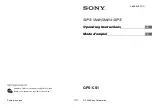
Pulse Mode: Rising
TIMEPULSE
TIMEPULSE
Pulse Mode: Falling
time
top of second
top of second
Pulse Period
Pulse Length
Figure 85: Example of a 1PPS Signal designed with TIMEPULSE
As
a
pulse
reference
GPS
or
UTC time
can
be
selected.
This
makes
a
difference
if
the
Pulse
Period
exceeds
1s.
As
the
TIMEPULSE
is
synchronized
with
GPS-
or
UTC-time
the
Pulse
Period
must
fulfill
the
following
condition:
n must be an integer value!
Note
The
Maximum
Pulse
Length
can’t
exceed
the
Pulse
Period
minus
1ms.
s
d
PulsePerio
n
60
=
⋅
GPS
Modules
-
System
Integration
Manual
(SIM)
(incl.
Reference
Design)
Receiver
Description
GPS.G4-MS4-05007-A1
Page 109