


your position is our focus
Standard Function
Remarks
No
Name
I/O
Description
1
BOOT_INT
I
Boot
mode
Leave
open
2
SELECT
Mode
Selector
Pin
EEPROM
is
used.
Never
leave
this
pin
open.
The
SELECT
pin
allows
selection
between
using
the
default
configuration
(Battery
Backup
RAM)
or
configuration
storage
in
an
external
EEPROM
(see
also
section
4.8
).
Connect
to
VCC
if
default
configuration
is
desired.
Connect
GND
if
external
g
of
pin
16
(
SCK / CFG_USB
)
depends
on
the
status
of
the
Note:
The
meanin
SELECT
pin.
3
TIMEPULSE
O
Time
pulse
(1PPS)
not
used.
See
also
Section 4.7.1
.
Configurable
Timepulse
signal
(one
pulse
per
second
by
default).
Leave
open
if
4
EXTINT0
I
External
Interrupt
Pin
External
Interrupt
Pin
to
wake
up
receiver
in
FixNOW™
sleep
mode.
See
also
Section 4.2.7.1
and
4.9.4
for
further
information.
Internal
pull-up
resistor
to
V_BAT
Leave
open
if
not
used.
5
USB_DM
I/O
USB
Data
6
atic
recommendation
in
Section 4.4.2.
USB_DP
I/O
USB
Data
USB1.1
bidirectional
communication
pin.
To
be
fully
compliant
with
USB
standard
follow
the
schem
7
VDDUSB
I
USB
Supply
If
To
use
the
USB
interface
connect
this
pin
to
3.0
–
3.6V.
See
also
Section 4.4.2.
no
USB
serial
port
used
connect
to
GND.
8
(Reserved)
I
Reserved
9
external
active
antenna.
VCC_RF
O
Output
Voltage
RF
section
Pins
8
and
9
have
to
be
connected.
VCC_RF
can
also
be
used
to
power
an
10
GND
I
Ground
Assure
a
good
GND
connection
to
all
GND
pins
of
the
module,
preferably
with
a
large
ground
plane
(for
details
refer
to
Section 0
)
11
RF_IN
I
GPS
signal
input
The
connection
to
the
antenna
has
to
be
routed
on
the
PCB.
Use
a
controlled
impedance
of
50
Ohm
to
connect
RF_IN
to
the
antenna
or
the
antenna
connector
(for
details
refer
to
Section 3.6.5)
12
fer
to
pin
10.
GND
I
Ground
Re
13
GND
I
Ground
Refer
to
pin
10.
14
MOSI
O
SPI
MOSI
15
MISO
I
SPI
MISO
Leave
open
if
SPI
interface
is
not
used.
Contact
u-blox
for
more
information
about
the
SPI
interface.
16
SCK
/
CFG_USB
O/I
SPI
Clock
/
USB
Power
Mode
The
function
of
pin
16
depends
on
the
status
of
the
SELECT
pin:
•
If SELECT pin is connected to VCC:
Pin
16
is
a
configuration
input,
which
defines
the
USB
Power
Mode.
Connect
to
GND
for
Bus-Powered
USB
interface.
Leave
open
if
USB
interface
Self-
Powered
•
If SELECT pin is connected to GND:
Pin
16
is
internally
connected
to
the
SCK
(SPI
clock
signal).
Contact
u-blox
for
more
information
about
the
SPI
interface.
17
NCS
O
SPI
chip
select
Leave
open
if
SPI
interface
is
not
used.
Contact
u-blox
for
more
information
about
the
SPI
interface.
18
(Reserved)
I
Leave
open
19
(Reserved)
I
NC
Leave
open
20
TxD1
O
Serial
Port
1
3V
Level
21
RxD1
I
Serial
Port
1
5V
tolerant
serial
input.
Internal
pull-up
resistor
to
V_BAT
.
Leave
open
if
not
used.
Note
Don’t
use
an
external
pull
up
resistor.
22
V_BAT
I
Backup
voltage
supply
It’s
recommended
to
connect
a
backup
battery
to
V_BAT
in
order
to
enable
Warm
and
Hot
Start
features
on
the
receivers.
See
also
Section 4.2.2
.
Otherwise
connect
to
GND
.
23
VCC
I
Supply
voltage
Max
allowed
ripple
on
VCC
=50mVpp
24
GND
I
Ground
Refer
to
pin
10.
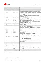
Table 7: Pin-out NEO-4S
7
Do
not
pull
up
as
it
may
increase
your
Battery
Backup
Current.
GPS
Modules
-
System
Integration
Manual
(SIM)
(incl.
Reference
Design)
Design-In
GPS.G4-MS4-05007-A1
Page 50