ST–12
2GR-FE STARTING
– SMART KEY SYSTEM
ST
4.
CONSTRUCTION AND OPERATION
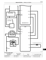
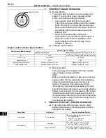
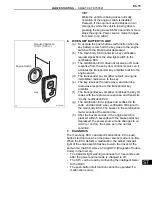
(a) Engine Switch
The engine switch consists of a momentary type
switch, 3 color (amber, green, greenish white)
LEDs, and a transponder key amplifier.
•
The greenish white LED is for illumination.
•
The amber and green LEDs are for the indicator
lights. The driver can check the present power
source mode and whether the engine can start in
accordance with the illumination state of the
indicator light.
•
When the main body ECU detects an
abnormality in the push-button start function, it
makes the amber indicator light flash. If the
engine stopped in this state, it may not be
possible to restart it.
(b) Indicator Light Condition
Engine switch indicator light condition:
(c) Main body ECU
The main body ECU consists of the IG1 and IG2
relay actuation circuits and CPU.
HINT:
Before removing the battery, make sure to turn the
engine switch off. The main body ECU constantly
stores the present power source mode in its
memory. Therefore, if the main body ECU is
interrupted by disconnecting the battery, the main
body ECU restores the power source mode after the
battery is reconnected. For this reason, if the battery
is disconnected when the engine switch is not off,
the power will be restored to the vehicle at the same
time the power is restored to the main body ECU (by
reconnecting the battery).
5.
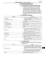
PUSH-BUTTON START FUNCTION OPERATION
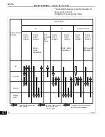
(a) This system has different power source mode
patterns depending on the brake pedal condition
and shift lever position.
START
STOP
Indicator Light
A109251E01
Power Source Mode/Condition
Indicator Light Condition
Brake pedal released
Brake pedal depressed, shift lever in P or N
off
OFF
ON (Green) (When key and vehicle IDs match)
on (ACC, IG)
ON (Amber)
ON (Green)
Engine running
OFF
OFF
Steering lock not unlocked
Flashes (Green) for 15 sec.
Flashes (Green) for 15 sec.
System malfunction
Flashes (Amber) for 15 sec.
Flashes (Amber) for 15 sec.
Brake Pedal
Shift Lever
Power Source Mode Pattern
Depressed
P or N position
When the engine switch is pushed once.
•
off
→
engine start
•
on (ACC)
→
engine start
•
on (IG)
→
engine start
Not depressed
P position
Each time the engine switch is pushed.
•
off
→
on (ACC)
→
on (IG)
→
off
Except P position
Each time the engine switch is pushed.
•
off
→
on (ACC)
→
on (IG)
→
on (ACC)
Содержание 2GR-FE
Страница 176: ...ES 20 2GR FE ENGINE CONTROL SYSTEM SFI SYSTEM ES NEXT 20 CONDUCT CONFIRMATION TEST END ...
Страница 247: ...2GR FE ENGINE CONTROL SYSTEM SFI SYSTEM ES 91 ES OK REPLACE ECM See page ES 518 ...
Страница 412: ...ES 256 2GR FE ENGINE CONTROL SYSTEM SFI SYSTEM ES A END ...
Страница 447: ...2GR FE ENGINE CONTROL SYSTEM SFI SYSTEM ES 291 ES OK REPLACE ECM See page ES 518 ...
Страница 556: ...ES 400 2GR FE ENGINE CONTROL SYSTEM SFI SYSTEM ES A REPLACE TCM ...
Страница 630: ...ES 474 2GR FE ENGINE CONTROL SYSTEM SFI SYSTEM ES OK REPLACE ECM See page ES 518 ...
Страница 651: ...2GR FE ENGINE CONTROL SYSTEM CAMSHAFT TIMING OIL CONTROL VALVE ASSEMBLY ES 487 ES 22 INSTALL ENGINE UNDER COVER LH ...
Страница 658: ...2GR FE ENGINE CONTROL SYSTEM VVT SENSOR ES 493 ES 22 INSTALL ENGINE UNDER COVER LH ...
Страница 719: ...FU 6 2GR FE FUEL FUEL SYSTEM FU PARTS LOCATION ENGINE ROOM RELAY BLOCK ECM FUEL INJECTOR FUEL PUMP A136014E01 ...
Страница 897: ...2GR FE STARTING SMART KEY SYSTEM ST 35 ST OK REPLACE MAIN BODY ECU ...
Страница 923: ...2GR FE STARTING SMART KEY SYSTEM ST 61 ST OK REPLACE MAIN BODY ECU ...
Страница 935: ...2GR FE STARTING SMART KEY SYSTEM ST 73 ST OK REPLACE MAIN BODY ECU ...
Страница 940: ...ST 78 2GR FE STARTING SMART KEY SYSTEM ST OK REPLACE MAIN BODY ECU ...
Страница 958: ...ST 96 2GR FE STARTING SMART KEY SYSTEM ST OK END MAIN BODY ECU DEFECTIVE ...


