2GR-FE ENGINE CONTROL SYSTEM
– SFI SYSTEM
ES–297
ES
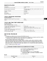
MONITOR STRATEGY
TYPICAL ENABLING CONDITIONS
Functional check:
TYPICAL MALFUNCTION THRESHOLDS
Functional check:
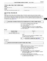
INSPECTION PROCEDURE
HINT:
•
The following conditions may also cause DTC P0505 to be set:
(a)The floor carpet overlapping onto the accelerator pedal, causing the accelerator pedal to be slightly
depressed and therefore the throttle valve position to be slightly open.
(b)The accelerator pedal being not fully released.
•
Read freeze frame data using the intelligent tester. The ECM records vehicle and driving condition
information as freeze frame data the moment a DTC is stored. When troubleshooting, freeze frame
data can be helpful in determining whether the vehicle was running or stopped, whether the engine
was warmed up or not, whether the air-fuel ratio was lean or rich, as well as other data recorded at the
time of a malfunction (See page
ES-45
).
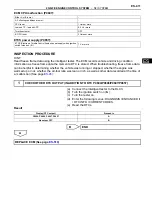
(a) Connect the intelligent tester to the DLC3.
(b) Turn the ignition switch on (IG).
(c) Turn the tester on.
(d) Enter the following the menus: DIAGNOSIS /
ENHANCED OBD II / DTC INFO / CURRENT CODES.
(e) Read the DTCs.
Result
Related DTCs
P0505: ISC function
Required Sensors/Components (Main)
ETCS
Required Sensors/Components (Sub)
Crankshaft position sensor, Engine coolant temperature sensor, and
Vehicle speed sensor
Frequency of Operation
Continuous
Duration
10 minutes
MIL Operation
2 driving cycles
Sequence of Operation
None
Monitor will run whenever these DTCs are not present
None
Engine
Running
Either of the following conditions 1 or 2 is met:
-
1. Frequency that following conditions (a) and (b) are met:
5 time or more
(a) Engine RPM - target engine RPM
Below -100 rpm, or 200 rpm or more
(b) Vehicle condition
Stop after vehicle was driven by 6.25 mph (10 km/h) or more
2. Frequency that following conditions (a) and (b) are met:
Once
(a) Engine RPM - target engine RPM
Below -100 rpm, or 200 rpm or more
(b) ISC flow rate learning value
1.3 L/sec. or less. or 8.5 L/sec. or more
1
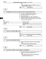
CHECK ANY OTHER DTCS OUTPUT (IN ADDITION TO DTC P0505)
Display (DTC output)
Proceed to
P0505
A
Содержание 2GR-FE
Страница 176: ...ES 20 2GR FE ENGINE CONTROL SYSTEM SFI SYSTEM ES NEXT 20 CONDUCT CONFIRMATION TEST END ...
Страница 247: ...2GR FE ENGINE CONTROL SYSTEM SFI SYSTEM ES 91 ES OK REPLACE ECM See page ES 518 ...
Страница 412: ...ES 256 2GR FE ENGINE CONTROL SYSTEM SFI SYSTEM ES A END ...
Страница 447: ...2GR FE ENGINE CONTROL SYSTEM SFI SYSTEM ES 291 ES OK REPLACE ECM See page ES 518 ...
Страница 556: ...ES 400 2GR FE ENGINE CONTROL SYSTEM SFI SYSTEM ES A REPLACE TCM ...
Страница 630: ...ES 474 2GR FE ENGINE CONTROL SYSTEM SFI SYSTEM ES OK REPLACE ECM See page ES 518 ...
Страница 651: ...2GR FE ENGINE CONTROL SYSTEM CAMSHAFT TIMING OIL CONTROL VALVE ASSEMBLY ES 487 ES 22 INSTALL ENGINE UNDER COVER LH ...
Страница 658: ...2GR FE ENGINE CONTROL SYSTEM VVT SENSOR ES 493 ES 22 INSTALL ENGINE UNDER COVER LH ...
Страница 719: ...FU 6 2GR FE FUEL FUEL SYSTEM FU PARTS LOCATION ENGINE ROOM RELAY BLOCK ECM FUEL INJECTOR FUEL PUMP A136014E01 ...
Страница 897: ...2GR FE STARTING SMART KEY SYSTEM ST 35 ST OK REPLACE MAIN BODY ECU ...
Страница 923: ...2GR FE STARTING SMART KEY SYSTEM ST 61 ST OK REPLACE MAIN BODY ECU ...
Страница 935: ...2GR FE STARTING SMART KEY SYSTEM ST 73 ST OK REPLACE MAIN BODY ECU ...
Страница 940: ...ST 78 2GR FE STARTING SMART KEY SYSTEM ST OK REPLACE MAIN BODY ECU ...
Страница 958: ...ST 96 2GR FE STARTING SMART KEY SYSTEM ST OK END MAIN BODY ECU DEFECTIVE ...


