ES–48
2GR-FE ENGINE CONTROL SYSTEM
– SFI SYSTEM
ES
DIAGNOSIS SYSTEM
1.
DESCRIPTION
When troubleshooting OBD II (On-Board Diagnostics)
vehicles, the intelligent tester (complying with SAE
J1987) must be connected to the DLC3 (Data Link
Connector 3) of the vehicle. Various data in the vehicle's
ECM (Engine Control Module) can be then read.
OBD ll regulations require that the vehicle's on-board
computer illuminates the MIL (Malfunction Indicator
Lamp) on the instrument panel when the computer
detects a malfunction in:
(a)The emission control systems and components.
(b)The power train control components (which affect
vehicle emissions).
(c) The computer itself.
In addition, the applicable DTCs (Diagnostic Trouble
Codes) prescribed by SAE J2012 are recorded on 3
consecutive trips, the MIL turns off automatically but the
DTCs remain recorded in the ECM memory.
To check for DTCs, connect the intelligent tester to the
DLC3. The tester displays DTCs, freeze frame data, and
a variety of the engine data. The DTCs and freeze frame
data can be erased with the tester. In order to enhance
OBD function on vehicles and develop the Off-Board
diagnosis system, CAN communication is introduced in
this system (CAN: Controller Area Network). It minimizes
a gap between technician skills and vehicle technology.
CAN is a network, which uses a pair of data transmission
lines, spanning multiple computers and sensors. It allows
a high speed communication between the systems and
simplification of the wire harness connection. Since this
system is equipped with the CAN communication,
connecting the CAN VIM (VIM: Vehicle Interface Module)
with the intelligent tester is necessary to display any
information from the ECM. (Also the communication
between the intelligent tester and the ECM uses CAN
communication signal). When confirming the DTCs and
any data of the ECM, connect the CAN VIM between the
DLC3 and the intelligent tester.
2.
NORMAL MODE AND CHECK MODE
The diagnosis system operates in normal mode during
normal vehicle use. In normal mode, 2 trip detection
logic is used to ensure accurate detection of
malfunctions. Check mode is also available as an option
for technicians. In check mode, 1 trip detection logic is
used for simulating malfunction symptoms and
increasing the system's ability to detect malfunctions,
including intermittent problems (intelligent tester only).
3.
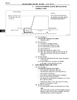
2 TRIP DETECTION LOGIC
When a malfunction is first detected, the malfunction is
temporarily stored in the ECM memory (1st trip). If the
same malfunction is detected during the next
subsequent drive cycle, the MIL is illuminated (2nd trip).
FI00534
Intelligent Tester
DLC3
C110200E01
Содержание 2GR-FE
Страница 176: ...ES 20 2GR FE ENGINE CONTROL SYSTEM SFI SYSTEM ES NEXT 20 CONDUCT CONFIRMATION TEST END ...
Страница 247: ...2GR FE ENGINE CONTROL SYSTEM SFI SYSTEM ES 91 ES OK REPLACE ECM See page ES 518 ...
Страница 412: ...ES 256 2GR FE ENGINE CONTROL SYSTEM SFI SYSTEM ES A END ...
Страница 447: ...2GR FE ENGINE CONTROL SYSTEM SFI SYSTEM ES 291 ES OK REPLACE ECM See page ES 518 ...
Страница 556: ...ES 400 2GR FE ENGINE CONTROL SYSTEM SFI SYSTEM ES A REPLACE TCM ...
Страница 630: ...ES 474 2GR FE ENGINE CONTROL SYSTEM SFI SYSTEM ES OK REPLACE ECM See page ES 518 ...
Страница 651: ...2GR FE ENGINE CONTROL SYSTEM CAMSHAFT TIMING OIL CONTROL VALVE ASSEMBLY ES 487 ES 22 INSTALL ENGINE UNDER COVER LH ...
Страница 658: ...2GR FE ENGINE CONTROL SYSTEM VVT SENSOR ES 493 ES 22 INSTALL ENGINE UNDER COVER LH ...
Страница 719: ...FU 6 2GR FE FUEL FUEL SYSTEM FU PARTS LOCATION ENGINE ROOM RELAY BLOCK ECM FUEL INJECTOR FUEL PUMP A136014E01 ...
Страница 897: ...2GR FE STARTING SMART KEY SYSTEM ST 35 ST OK REPLACE MAIN BODY ECU ...
Страница 923: ...2GR FE STARTING SMART KEY SYSTEM ST 61 ST OK REPLACE MAIN BODY ECU ...
Страница 935: ...2GR FE STARTING SMART KEY SYSTEM ST 73 ST OK REPLACE MAIN BODY ECU ...
Страница 940: ...ST 78 2GR FE STARTING SMART KEY SYSTEM ST OK REPLACE MAIN BODY ECU ...
Страница 958: ...ST 96 2GR FE STARTING SMART KEY SYSTEM ST OK END MAIN BODY ECU DEFECTIVE ...


