2GR-FE ENGINE CONTROL SYSTEM
– SFI SYSTEM
ES–257
ES
MONITOR DESCRIPTION
The ECM uses the sensors mounted in front of and behind the Three-Way Catalytic Converter (TWC) to
monitor its efficiency.
The first sensor, the Air-Fuel Ratio (A/F) sensor, sends pre-catalyst information to the ECM. The second
sensor, the Heated Oxygen (HO2) sensor, sends post-catalyst information to the ECM.
In order to detect any deterioration in the TWC, the ECM calculates the Oxygen Storage Capacity (OSC)
of the TWC. This calculation is based on the voltage output of the HO2 sensor while performing active air-
fuel ratio control, rather than the conventional detecting method, which uses the locus ratio.
The OSC value is an indication of the oxygen storage capacity of the TWC. When the vehicle is being
driven with a warm engine, active air-fuel ratio control is performed for approximately 15 to 20 seconds.
When it is performed, the ECM deliberately sets the air-fuel ratio to lean or rich levels. If a rich-lean cycle
of the HO2 sensor is long, the OSC becomes greater. There is a direct correlation between the OSCs of
the HO2 sensor and the TWC.
The ECM uses the OSC value to determine the state of the TWC. If any deterioration has occurred, it
illuminates the MIL and sets a DTC.
HINT:
•
Bank 1 refers to the bank that includes cylinder No. 1.
•
Bank 2 refers to the bank that does not include cylinder No. 1.
•
Sensor 1 refers to the sensor closest to the engine assembly.
•
Sensor 2 refers to the sensor farthest away from the engine assembly.
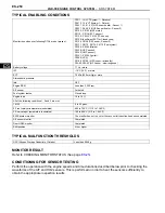
MONITOR STRATEGY
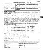
DTC
P0420
Catalyst System Efficiency Below Threshold
(Bank 1)
DTC
P0430
Catalyst System Efficiency Below Threshold
(Bank 2)
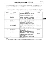
DTC No.
DTC Detection Condition
Trouble Area
P0420
OSC value is smaller than standard value under active
air-fuel ratio control (2 trip detection logic)
•
Gas leakage from exhaust system
•
A/F sensor (bank 1 sensor 1)
•
HO2 sensor (bank 1 sensor 2)
•
Exhaust manifold (TWC)
P0430
OSC value is smaller than standard value under active
air-fuel ratio control (2 trip detection logic)
•
Gas leakage from exhaust system
•
A/F sensor (bank 2 sensor 1)
•
HO2 sensor (bank 2 sensor 2)
•
Exhaust manifold (TWC)
Related DTCs
P0420: Catalyst Deterioration
P0420: Catalyst Deterioration
Required Sensors/Components (Main)
TWC
Required Sensors/Components (Sub)
A/F sensor, heated oxygen sensor, intake air temperature sensor, mass air flow
meter, crankshaft position sensor and engine coolant temperature sensor
Frequency of Operation
Once per driving cycle
Duration
Approximately 30 seconds
MIL Operation
2 driving cycles
Sequence of Operation
None
Содержание 2GR-FE
Страница 176: ...ES 20 2GR FE ENGINE CONTROL SYSTEM SFI SYSTEM ES NEXT 20 CONDUCT CONFIRMATION TEST END ...
Страница 247: ...2GR FE ENGINE CONTROL SYSTEM SFI SYSTEM ES 91 ES OK REPLACE ECM See page ES 518 ...
Страница 412: ...ES 256 2GR FE ENGINE CONTROL SYSTEM SFI SYSTEM ES A END ...
Страница 447: ...2GR FE ENGINE CONTROL SYSTEM SFI SYSTEM ES 291 ES OK REPLACE ECM See page ES 518 ...
Страница 556: ...ES 400 2GR FE ENGINE CONTROL SYSTEM SFI SYSTEM ES A REPLACE TCM ...
Страница 630: ...ES 474 2GR FE ENGINE CONTROL SYSTEM SFI SYSTEM ES OK REPLACE ECM See page ES 518 ...
Страница 651: ...2GR FE ENGINE CONTROL SYSTEM CAMSHAFT TIMING OIL CONTROL VALVE ASSEMBLY ES 487 ES 22 INSTALL ENGINE UNDER COVER LH ...
Страница 658: ...2GR FE ENGINE CONTROL SYSTEM VVT SENSOR ES 493 ES 22 INSTALL ENGINE UNDER COVER LH ...
Страница 719: ...FU 6 2GR FE FUEL FUEL SYSTEM FU PARTS LOCATION ENGINE ROOM RELAY BLOCK ECM FUEL INJECTOR FUEL PUMP A136014E01 ...
Страница 897: ...2GR FE STARTING SMART KEY SYSTEM ST 35 ST OK REPLACE MAIN BODY ECU ...
Страница 923: ...2GR FE STARTING SMART KEY SYSTEM ST 61 ST OK REPLACE MAIN BODY ECU ...
Страница 935: ...2GR FE STARTING SMART KEY SYSTEM ST 73 ST OK REPLACE MAIN BODY ECU ...
Страница 940: ...ST 78 2GR FE STARTING SMART KEY SYSTEM ST OK REPLACE MAIN BODY ECU ...
Страница 958: ...ST 96 2GR FE STARTING SMART KEY SYSTEM ST OK END MAIN BODY ECU DEFECTIVE ...


