


2-100
Service Manual
5060-XXX
Step A
Step B
Step C
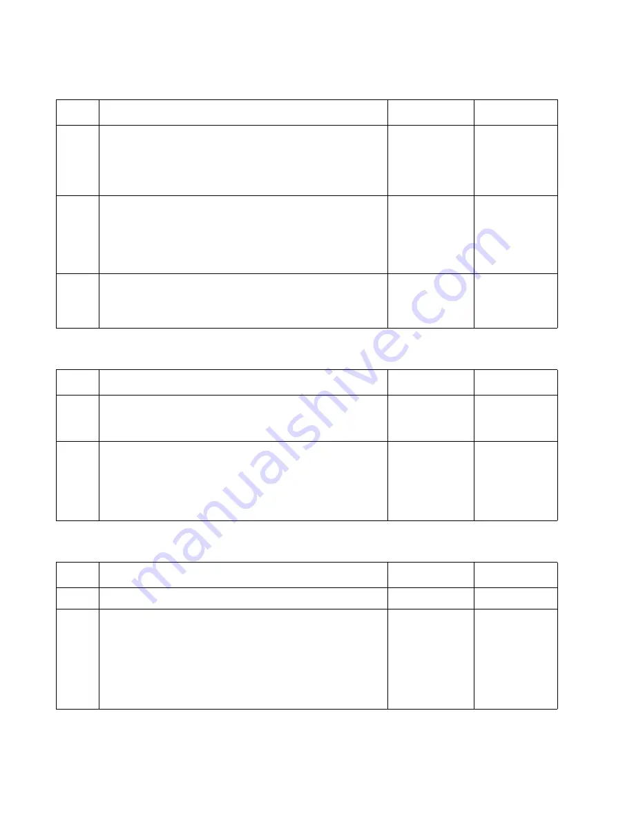
Step
Action and Questions
Yes
No
1
Use the Tray 1 feed test to feed paper from Tray 1. Check to
see if the Pick Rolls are turning?
Note: You can observe the pick rolls by opening the Lower
Jam access door assembly.
Do the Pick Rolls Turn?
Go to step 2
Go to step 3
2
Check the Autocompensator Pick Rolls for any signs of
contamination or damage to the rolls.
Is there any excessive contamination or damage to the Pick
Rolls?
Replace the
Pick Rolls.
Always replace
both pick rolls
at the same
time.
Go to step 3
3
Check the voltages at J73 on the Engine Board.
Are the voltages correct?
Replace the
Autocompen-
sator
Assembly
Replace the
“Engine
Board” on
page 4-14
Step
Action and Questions
Yes
No
1
Check Tray 1 for any signs of damage to the Pick Arm Lift
Bellcrank activation tabs on the rear of the tray.
Is there any damage to the tray?
Replace Tray 1
Go to step 2
2
Check the following parts for any signs of damaged, loose
or missing parts.
Pick Arm Lift Bellcrank
Bellcrank Lift Spring
Tray interlock bellcrank
Are any of the parts broken, loose or missing?
Repair or
replace parts
as necessary
Replace the
Autocompen-
sator
Assembly
Step
Action and Questions
Yes
No
1
Can you remove Tray 1 from the printer?
Go to step 3
Go to step 2
2
Open the Lower Jam Access door and carefully lift the
autocompensator assembly until it is in it's upper most
position, and carefully try to remove Tray 1.
Can you remove Tray 1?
Go to step 3
Determine
what is
causing the
tray to stay in
a locked
position.
Repair as
necessary
Содержание e-STUDIO 20CP
Страница 2: ...COLORPRINTER e STUDIO20CP ...
Страница 3: ... ii ...
Страница 5: ......
Страница 19: ...xvi Service Manual 5060 XXX ...
Страница 37: ...1 18 Service Manual 5060 XXX ...
Страница 161: ...2 124 Service Manual 5060 XXX ...
Страница 200: ...Repair Information 4 15 5060 XXX 4 Remove the right rear cover screw type 121 on page 4 4 A ...
Страница 246: ...Connector Locations 5 17 5060 XXX RIP Board ...
Страница 254: ...Connector Locations 5 25 5060 XXX HVPS Board ...
Страница 256: ...Connector Locations 5 27 5060 XXX HVPS Developer Board ...
Страница 257: ...5 28 Service Manual 5060 XXX ...
Страница 261: ...7 2 Service Manual 5060 XXX Assembly 1 Covers ...
Страница 263: ...7 4 Service Manual 5060 XXX Assembly 1 1 Covers ...
Страница 269: ...7 10 Service Manual 5060 XXX Assembly 5 Paper Feed Output Redrive ...
Страница 271: ...7 12 Service Manual 5060 XXX Assembly 6 Multipurpose Feeder MPF ...
Страница 273: ...7 14 Service Manual 5060 XXX Assembly 7 500 Sheet Integrated Tray ...
Страница 277: ...7 18 Service Manual 5060 XXX Assembly 9 1 ITU Assembly ...
Страница 279: ...7 20 Service Manual 5060 XXX Assembly 10 Cartridge Contact Assembly ...
Страница 281: ...7 22 Service Manual 5060 XXX Assembly 11 Electronics ...
Страница 283: ...7 24 Service Manual 5060 XXX Assembly 11 1 Electronics ...
Страница 291: ...7 32 Service Manual 5060 XXX Assembly 12 Output Expander ...
Страница 293: ...7 34 Service Manual 5060 XXX Assembly 12 1 Output Expander ...
Страница 295: ...7 36 Service Manual 5060 XXX Assembly 13 5 Bin Mailbox ...
Страница 297: ...7 38 Service Manual 5060 XXX Assembly 13 1 5 Bin Mailbox ...
Страница 299: ...7 40 Service Manual 5060 XXX Assembly 14 500 Sheet Tray Option ...
Страница 301: ...7 42 Service Manual 5060 XXX Assembly 14 1 500 Sheet Tray Option ...
Страница 303: ...7 44 Service Manual 5060 XXX Assembly 15 Duplex Unit ...
Страница 305: ...7 46 Service Manual 5060 XXX Assembly 15 1 Duplex Unit ...
Страница 307: ...7 48 Service Manual 5060 XXX Assembly 16 HCIT ...
Страница 309: ...7 50 Service Manual 5060 XXX Assembly 16 1 HCIT ...
Страница 323: ...I 8 Service Manual 5060 XXX ...


