DRIVE SYSTEM
7-48
Rev. 000
TX525 Service Manual
Left Hydrostatic Pump Installation
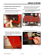
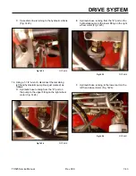
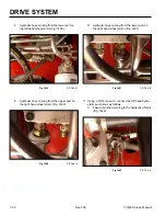
Fig 1443
PICT-4627
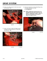
2. Using a 3/4” socket and wrench, install the top bolt
and nut. Tighten the lower bolt and nut securing the
left hand hydrostatic pump to the tower frame (Fig.
1444).
Fig 1444
PICT-4619
1. With the lower bolt and nut loosely installed in the
tower frame, position the left hand hydrostatic pump
so the pump shaft is inserted through the frame (Fig.
1443).
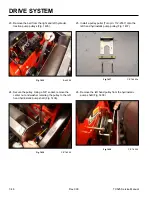
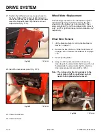
3. Install a key into the hydrostatic pump shaft keyway
(Fig. 1445).
Fig 1445
PICT-4598
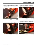
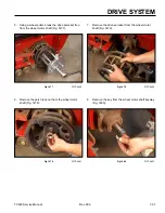
4. The pulley has a tapered through hole and a thicker
flange on one side (Fig. 1446).
Fig 1446
PICT-4659
Содержание Dingo TX 525
Страница 1: ...TX525 Service Manual Sitework Systems Form No 492 9195...
Страница 3: ...ii Rev 000 TX525 Service Manual 8 01 10 Revision 000 REVISIONS...
Страница 11: ...x Rev 000 TX525 Service Manual TABLE OF CONTENTS THIS PAGE INTENTIONALLY LEFT BLANK...
Страница 243: ...ENGINE 4 190 Rev 000 TX525 Service Manual THIS PAGE INTENTIONALLY LEFT BLANK...
Страница 263: ...ELECTRICAL 5 20 Rev 000 TX525 Service Manual THIS PAGE INTENTIONALLY LEFT BLANK...
Страница 377: ...HYDRAULIC SYSTEM 6 114 Rev 000 TX525 Service Manual THIS PAGE INTENTIONALLY LEFT BLANK...
Страница 479: ...DRIVE SYSTEM 7 102 Rev 000 TX525 Service Manual THIS PAGE INTENTIONALLY LEFT BLANK...
Страница 533: ...BRAKES 8 54 Rev 000 TX525 Service Manual 12 Install the rear access panel Fig 1836 Fig 1836 PICT 4505a...
Страница 553: ...HYDRAULIC TESTING 9 20 Rev 000 TX525 Service Manual THIS PAGE INTENTIONALLY LEFT BLANK...
Страница 554: ...TX525 Service Manual Form No 492 9195...


