background image

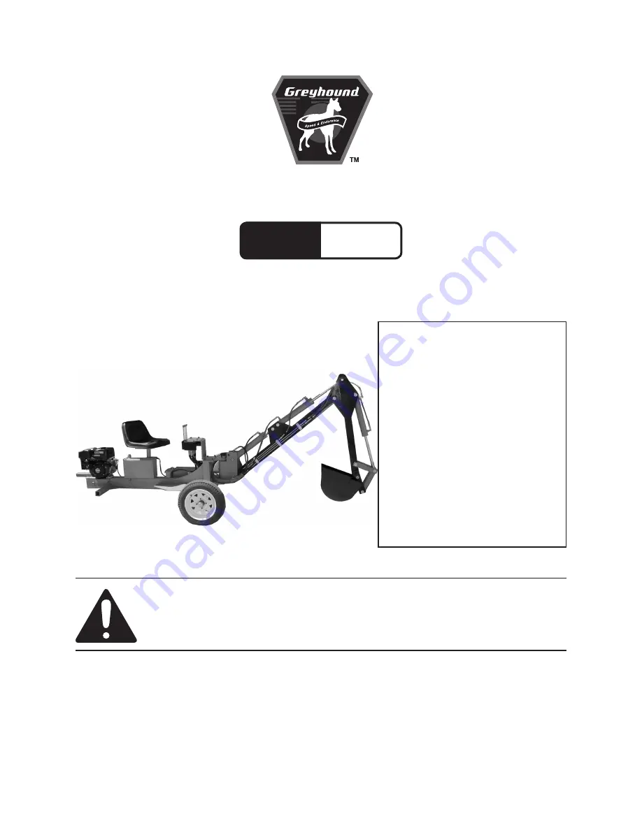
9 HP ride-on trencHer

Model

65162

Set uP, oPerating, and Servicing 

inStructionS


Warning!

iMPortant inForMation

The  Hitch  Coupler  MUST  be  properly 

secured to the hitch ball of the towing vehicle.  

After assembly and attachment, pull up and 

down on the Hitch Coupler to make sure the 

hitch ball is fitting snugly in the Hitch Coupler.  

there must be no play between the hitch 

ball and Hitch coupler.

  If there is play, tighten 

the Adjustment Nut until no play is present.  If 

the Adjustment  Nut  is  too  tight,  the  Handle 

will  not  lock.   

carefully  read  and  follow 

the  complete  instructions  in  this  manual 

BeFore setup or use.

if  the  coupler  is  not  secured 

properly,  the  ball  could  come  loose 

while  the  Log  Splitter  is  in  motion, 

possibly  causing  property  damage, 

SeriouS  PerSonaL  injury,  or 

deatH.

visit our website at: http://www.harborfreight.com

 read this material before using this product.  

Failure to do so can result in serious injury. 

Save tHiS ManuaL.

Copyright

©

 2008 by Harbor Freight Tools

®

.  All rights reserved.  No portion of this 

manual or any artwork contained herein may be reproduced in any shape or form 

without the express written consent of Harbor Freight Tools.  Diagrams within this 

manual may not be drawn proportionally.  Due to continuing improvements, actual 

product may differ slightly from the product described herein.  Tools required for 

assembly and service may not be included.

For technical questions or replacement parts, please call 1-800-444-3353.

Revised 11a

Содержание 65162

Страница 1: ...ot secured properly the ball could come loose while the Log Splitter is in motion possibly causing property damage serious personal injury or death Visit our website at http www harborfreight com Read...

Страница 2: ...19 Maintenance Procedures 19 Engine Oil Change 19 Air Filter Element Maintenance 19 Spark Plug Maintenance 20 Fuel Filter Replacement if equipped 20 Cleaning Maintenance and Lubrication Schedule 21 A...

Страница 3: ...etor parts list diagram 34 Flywheel coil assembly parts list diagram 35 Control system parts list diagram 36 Air cleaner parts list diagram 37 Muffler parts list diagram 38 Fuel tank parts list diagra...

Страница 4: ...ion which if not avoided could result in minor or moderate injury NOTICE is used to address practices not related to personal injury CAUTION without the safety alert symbol is used to address practice...

Страница 5: ...se only accessories that are 6 recommended by Harbor Freight Tools for your model Accessories that may be suitable for one piece of equipment may become hazardous when used on another piece of equipme...

Страница 6: ...cool b Then remove the spark plug c wire s from the spark plug s Keep all safety guards in place and 2 in proper working order Safety guards include muffler air cleaner mechanical guards and heat shi...

Страница 7: ...st created by 3 power sanding sawing grinding drilling and other construction activities contains chemicals known to the State of California to cause cancer birth defects or other reproductive harm So...

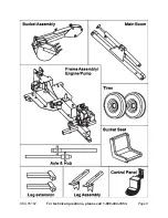
Страница 8: ...o prevent damage to the engine and any other devices used with this product Unpacking When unpacking check to make sure that the item is intact and undamaged If any parts are missing or broken please...

Страница 9: ...Page 9 SKU 65162 For technical questions please call 1 800 444 3353...

Страница 10: ...safety goggles and other protective gear to prevent injury from leaking fluid Attach the Main Boom 36 to the 9 Boom Pivot 38 using the Pin 42 through the bottom hole and Clevis Pin No 1 29 through the...

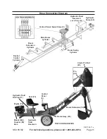
Страница 11: ...29 Seat 73 Hydraulic Fluid Reservoir Hydraulic Fluid Fill Plug 11 TOW CONFIGURATION Engine 74 Frame Assy 90 Mount Hitch Coupler 58 Here Control Panel 9 Bucket Control Cylinder Boom Extension Cylinder...

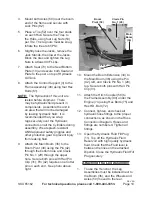
Страница 12: ...2 82 Purging the Cylinder Remove all Safety Locking Pins 15 1 disengage the Safety Latch 41 and loosen Hydraulic Tank Fill Plug 11 Press forward on the Boom Swing 2 Lever located on Control Panel 9 u...

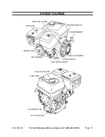
Страница 13: ...353 Engine diagram COMPONENTS CONTROL LOCATIONS 3 2 COMPONENTS CONTROL LOCATIONS THROTTLE LEVER MUFFLER SPARK PLUG AIR CLEANER FUEL VALVE LEVER CHOKE LEVER RECOIL STARTER STARTER GRIP IGNITION SWITCH...

Страница 14: ...n the Fuel Filler Cap and the 1 area around it To Check the fuel level unscrew and 1 remove the Fuel Filler Cap Mix fuel stabilizer not included 2 with 86 octane or better unleaded gasoline according...

Страница 15: ...ional break in period will 2 last about 3 hours of use During this period Do not apply a heavy load to the equipment Do not operate the engine at its maximum speed The maintenance break in period will...

Страница 16: ...0 degrees left and 60 degrees right Press in on the Bucket control handle 10 to dump the load Moving the Trencher One method for moving the trencher 11 around the work area is by using the Boom to pus...

Страница 17: ...ng it in place When transporting the Trencher 19 make sure your hitch not included is compatible with the Hitch Coupler 92 Follow all of the safety warnings for towing in your vehicle s manual The Hit...

Страница 18: ...rear bumper or frame CAUTION Care must be taken 24 when backing up the Trencher Only back up the Trencher on a straight path If the Trencher is allowed to turn off the straight path while backing up t...

Страница 19: ...oblem corrected before further use Maintenance Procedures Many maintenance procedures including any not detailed in this manual will need to be performed by a qualified technician for safety If you ha...

Страница 20: ...then turn about 1 2 2 3 more Non gasket style Finger tighten until the plug contacts the head then turn about 1 16 more Apply dielectric spark plug boot 6 protector not included to the end of the spar...

Страница 21: ...engine for storage as follows Change engine oil and empty fuel a tank Either leave fuel tank empty or b refill fuel tank with fresh unleaded gasoline mixed with a fuel stabilizer intended for long te...

Страница 22: ...Page 22 SKU 65162 For technical questions please call 1 800 444 3353 Lubrication Points 38 36...

Страница 23: ...mber Reinstall spark plug and set choke to start position Ignition spark Related Spark plug wire not connected 1 securely Spark plug electrode wet or dirty 2 Incorrect spark plug gap 3 Spark plug wire...

Страница 24: ...ther mechanical problems Fill fuel tank with fresh 86 octane 1 unleaded gasoline Do not exceed equipment s load 2 rating Have qualified technician diagnose 3 and service engine Engine backfires Impure...

Страница 25: ...SE ASSEMBLY NO 5 1 71 ENGINE KEY 1 22 HOSE ASSEMBLY NO 10 1 72 HEX HD BOLT 5 16 1 3 4 4 23 CONTROL PANEL 1 73 SEAT 1 24 LEG ASSEMBLY 2 74 ENGINE 1 25 90 ELBOW FITTING NO 1 8 75 HEX HD BOLT 5 16 4 26 C...

Страница 26: ...eneral Assembly diagram REV 09f Record Product s Serial Number Here Note If product has no serial number record month and year of purchase instead Note Some parts are listed and shown for illustration...

Страница 27: ...Tube 1 8B Spark Plug 1 9B Cylinder Gasket 1 10B Muffler Gasket 1 11B Pin 2 12B Bolt 6x14 4 13B Bolt 8x55 4 14B Intake Bolt 2 15B Exhaust Bolt 2 16B Intake Valve Seat 1 17B Exhaust Valve Seat 1 18B Cy...

Страница 28: ...ain Plug 2 10C Washer 2 11C Washer 2 12C Clip 1 Part Description Qty 13C Ball Bearing 1 14C Oil Seal 1 15C O ring 1 16C Nut 1 17C Washer 1 18C R pin 1 19C Bolt 6x12 3 20C Shaft 1 21C Governor Assembly...

Страница 29: ...tick 1 3D Gasket 2 4D Cover 1 5D Oil Seal 1 6D Bearing 1 7D Pin 2 8D Oil Filler Cap 1 9D Gasket Case Cover 1 10D Oil Fill Assembly 1 11D Cap Assembly 1 Note When ordering replacement parts from this d...

Страница 30: ...bly 1 6E Bolt 2 7E Clip 2 8E Timing Gear 1 9E Gear 1 10E Crankshaft 1 11E First Ring 1 12E Second Ring 1 13E Oil Ring 2 14E Bushing Ring 1 15E Connecting Rod 1 16E Connecting Rod Bearing Cap 1 17E Key...

Страница 31: ...ve Spring Retainer 2 12F Valve Spring 2 13F Guide Seal 1 Part Description Qty 14F Camshaft Assembly 1 15F Reducer Pin 1 16F Reducer 1 17F Matching Block Pin 2 18F Matching Block 1 19F Flying Block Pin...

Страница 32: ...ing 2 7G Recoil Starter Reel 1 8G Recoil Starter Spring 1 9G Recoil Starter Knob 1 10G Fan Cover 1 11G Rope 1 12G Bolt 6x8 3 13G Bolt 6x10 4 14G Fan Cover 1 15G Switch Assembly 1 16G Recoil Starter 1...

Страница 33: ...m Part Description Qty 1H Bolt 6x20 1 2H Side Plate 1 3H Bolt 6x8 2 4H Shroud 1 5H Side Plate 1 6H Grommet 1 Note When ordering replacement parts from this diagram use the suffix H Note Some parts are...

Страница 34: ...Gasket Bolt 1 12J Bolt 1 13J Drain Bolt 1 14J Drain Bolt Gasket 1 15J Fuel Strainer Cup 1 16J Fuel Strainer Cup Packing 1 17J Fuel Packing 1 18J Lever 1 Part Description Qty 19J Lever Spring 1 20J Se...

Страница 35: ...4K Stop Switch Cord 1 5K Bolt 6x30 2 6K Flywheel Cover 1 7K Charge Coil Assembly 1 8K Cooling Fan 1 9K Starter Pulley 1 10K Nut 1 11K Flywheel 1 12K Charge Coil 1 13K Bolt 6x35 2 14K Cord Clamp 1 15K...

Страница 36: ...1 9M Nut 1 10M Fixing Plate 1 11M Washer 1 Part Description Qty 12M Washer 1 13M Retainer Assembly 1 14M Spring 1 15M Screw 5x35 16M Cable Return Spring 1 17M Control Handle 1 18M Screw 5x25 1 19M Bac...

Страница 37: ...lt 6x20 1 7N Nut 6mm 2 8N Nut 2 9N Air Cleaner Cover 1 Part Description Qty 10N Air Cleaner Element Assembly 1 11N Grommet 1 12N Outer Filter 1 13N Element 1 14N Base 1 15N Air Cleaner Assembly 1 16N...

Страница 38: ...ption Qty 1P Muffler 1 2P Nut 8mm 1 3P Muffler Cover 1 4P Screw 5x8 4 5P Muffler Assembly 1 6P Muffler Case 1 Note When ordering replacement parts from this diagram use the suffix P Note Some parts ar...

Страница 39: ...ller Assembly 1 5R Fuel Cap Gasket 1 6R Fuel Strainer 1 7R Bolt 6x25 1 8R Joint Packing 1 9R Nut 6mm 2 10R Fuel Line 1 11R Fuel Cap 1 12R Fuel Tank Assembly 1 13R Adapter Connector 1 Note When orderin...

Страница 40: ...paired products at our expense but if we determine there is no defect or that the defect resulted from causes not within the scope of our warran ty then you must bear the cost of returning the product...

Страница 41: ...filed in accordance with the provi sions of the HFT warranty policy explained in the box at the top of the previous page HFT shall not be liable for any loss of use of the engine for any alternative...

Страница 42: ......

Страница 43: ...HV Cooling System Forced air cooled Fuel Type 87 octane unleaded gasoline Capacity 1 Gallon Engine Oil Type SAE 10W 30 above 32 F 5W30 at 32 F or below Capacity 1 16 Quart Run Time 50 Load with full t...

Страница 44: ...far away from windows doors and vents WARNING marking concerning Risk of Fire while handling fuel Do not smoke while handling fuel WARNING marking concerning Risk of Fire Do not refuel while operatin...

Страница 45: ...r a full face shield along with steel toed work boots during use 13 People with pacemakers should consult their physician s before use Electromagnetic fields in close proximity to a heart pacemaker co...

Страница 46: ...er or adjust any part of the equipment or its engine that is sealed by the manufacturer or distributor Only a qualified service technician may adjust parts that may increase or decrease governed engin...

Страница 47: ...520 0882 280cc Engine SAFETY OpERATION MAINTENANCE SETUp Engine Controls Starter Handle Oil Drain plug Air Filter Muffler Fuel Valve Choke Fuel Cap Throttle Dipstick Serial Number Location Write near...

Страница 48: ...tion of this equipment may create sparks that can start fires around dry vegetation A spark arrestor may be required The operator should contact local fire agencies for laws or regulations relating to...

Страница 49: ...ty Grade chart on page 12 in the Service section shows other viscosities to use in different average temperatures 6 Thread the dipstick back in clockwise CAUTION Do not run the engine with too little...

Страница 50: ...d elsewhere on the tool which functions the same as the Throttle Use the Speed Control Lever in place of the Throttle when the tool is so equipped 4 Turn the Engine Switch on 5 Grip the Starter Handle...

Страница 51: ...ne will help to ensure proper equipment and engine operation b The operational break in period will last about 3 hours of use During this period Do not apply a heavy load to the equipment Do not opera...

Страница 52: ...general guide If performance decreases or if equipment operates unusually check systems immediately The maintenance needs of each piece of equipment will differ depending on factors such as duty cycl...

Страница 53: ...oil 1 Make sure the engine is stopped and is level 2 Close the Fuel Valve 3 Place a drain pan not included underneath the crankcase s drain plug 4 Remove the drain plug and if possible tilt the crankc...

Страница 54: ...NOTICE Do not clean using water The water will gradually enter the engine and cause rust damage Apply a thin coat of rust preventive oil to all metal parts 2 FUEL WARNING TO pREVENT SERIOUS INJURY FRO...

Страница 55: ...r with screwdriver handle 8 Turn Choke to RUN position Remove spark plug and pull the start handle several times to air out the chamber Reinstall spark plug and set Choke to CHOKE position 9 Replace F...

Страница 56: ...y Do not use gasoline with more than 10 ethanol E15 E20 E85 etc 3 Test replace fuel tank cap 4 Have qualified technician service magneto 5 Secure spark plug cap Engine stops when under heavy load 1 Di...

Страница 57: ...exclusion or limitation of incidental or consequential damages so the above limitation of exclusion may not apply to you THIS WARRANTY IS EXPRESSLY IN LIEU OF ALL OTHER WARRANTIES EXPRESS OR IMPLIED...

Страница 58: ...ears after the date of delivery to the first retail purchaser 2 No Charge Repair or Replacement Repair or replacement of any warranted part will be performed at no charge to the owner if the work is p...

Страница 59: ...Valve Adjusting Nut Valve Adjusting 2 57 Nut Valve Lock 2 58 Spring Valve Spring Valve 2 59 Retainer Valve Spring Spring 1 60 Starter Asm Recoil 1 61 Bolt 3 62 Shroud 1 63 Shroud Cylinder Shroud Cylin...

Страница 60: ...Page 19 For technical questions please call 1 800 520 0882 280cc Engine SAFETY OpERATION MAINTENANCE SETUp Assembly Diagram...

Страница 61: ...5mm 2 2 in 56mm 1 1 in 28mm 1 375 in 35mm 2 84 in 72 2mm 7 16 20 UNF 1 in 25 4mm 1 in 25 4mm 0 25 in 6 3mm 0 36 in 9 13mm 5 43 in 138mm 6 5 in 165 1mm 4 45 in 113mm 4 45 in 113mm 4 45 in 113mm 4 45 i...

Отзывы: