ELECTRICAL
5-7
TX525 Service Manual
Rev. 000
Water Temperature and Glow Plug
Indicator Light Cluster
How It Works
Testing - Oil Pressure Light
Testing - Battery Charge Light
Purpose
Location
The water temperature indicator light notifies the oper
ator when the engine coolant gets too hot. An audible
alarm will also sound.
The glow plug indicator light notifies the operator
while the glow plugs are warming the pre-cumbustion
chamber.
1A-1B: Engine oil pressure light terminals
2A-2B: Battery charge light terminals
The Water Temperature and Glow Plug Indicator Light
Cluster is located in the center of the control panel (Fig.
0810).
Disconnect the wire harness plug from the light cluster.
Connect 12v (+) to the “1A” terminal and connect ground
(-) to the “1B” terminal. If the light does not illuminate
replace the light assembly (Fig. 0809).
Connect 12v (+) to the “2A” terminal and connect ground
(-) to the “2B” terminal. If the light does not illuminate
replace the light assembly (Fig. 0809).
If indicator lights test OK, check the circuit wiring and
Oil Pressure Switch. The green wire from the voltage
regulator needs to have battery voltage to keep the light
from illuminating.
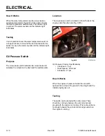
If the engine oil pressure gets too low, the engine oil
pressure light illuminates and an audible alarm sounds.
If the battery charge becomes too low, the battery
charge indicator light illuminates.
Fig 0810
PICT-5296
Fig 0809
PICT-5294a
A. Water Temperature Light
B. Glow Plug Indicator Light
A
B
1A
1B
2A
2B
Содержание Dingo TX 525
Страница 1: ...TX525 Service Manual Sitework Systems Form No 492 9195...
Страница 3: ...ii Rev 000 TX525 Service Manual 8 01 10 Revision 000 REVISIONS...
Страница 11: ...x Rev 000 TX525 Service Manual TABLE OF CONTENTS THIS PAGE INTENTIONALLY LEFT BLANK...
Страница 243: ...ENGINE 4 190 Rev 000 TX525 Service Manual THIS PAGE INTENTIONALLY LEFT BLANK...
Страница 263: ...ELECTRICAL 5 20 Rev 000 TX525 Service Manual THIS PAGE INTENTIONALLY LEFT BLANK...
Страница 377: ...HYDRAULIC SYSTEM 6 114 Rev 000 TX525 Service Manual THIS PAGE INTENTIONALLY LEFT BLANK...
Страница 479: ...DRIVE SYSTEM 7 102 Rev 000 TX525 Service Manual THIS PAGE INTENTIONALLY LEFT BLANK...
Страница 533: ...BRAKES 8 54 Rev 000 TX525 Service Manual 12 Install the rear access panel Fig 1836 Fig 1836 PICT 4505a...
Страница 553: ...HYDRAULIC TESTING 9 20 Rev 000 TX525 Service Manual THIS PAGE INTENTIONALLY LEFT BLANK...
Страница 554: ...TX525 Service Manual Form No 492 9195...


