DRIVE SYSTEM
7-63
TX525 Service Manual
Rev. 000
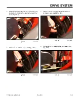
3. Position the wheel motor mounting plate on the
inside of the frame with the wide side positioned
toward the rear of the machine (Fig. 1500).
Fig 1500
PICT-4477
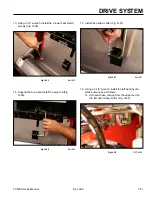
4. Apply a thread locking compound to the threads of
the wheel motor mounting bolts (Fig. 1501).
Fig 1501
PICT-4474a
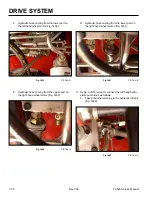
5. Install the 4 mounting bolts and lock washers
through the wheel motor housing and frame. The top
2 mounting bolts will also thread into the mounting
plate. Torque the 4 mounting bolts to 75 ± 8 ft-lbs.
(102 ± 11 Nm) (Fig. 1502).
Fig 1502
PICT-4479
6. Remove protective caps.
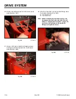
7. With a 1-1/16” socket, install the hydraulic fittings
into the wheel motor (Fig. 1503).
Fig 1503
PICT-4463
Содержание Dingo TX 525
Страница 1: ...TX525 Service Manual Sitework Systems Form No 492 9195...
Страница 3: ...ii Rev 000 TX525 Service Manual 8 01 10 Revision 000 REVISIONS...
Страница 11: ...x Rev 000 TX525 Service Manual TABLE OF CONTENTS THIS PAGE INTENTIONALLY LEFT BLANK...
Страница 243: ...ENGINE 4 190 Rev 000 TX525 Service Manual THIS PAGE INTENTIONALLY LEFT BLANK...
Страница 263: ...ELECTRICAL 5 20 Rev 000 TX525 Service Manual THIS PAGE INTENTIONALLY LEFT BLANK...
Страница 377: ...HYDRAULIC SYSTEM 6 114 Rev 000 TX525 Service Manual THIS PAGE INTENTIONALLY LEFT BLANK...
Страница 479: ...DRIVE SYSTEM 7 102 Rev 000 TX525 Service Manual THIS PAGE INTENTIONALLY LEFT BLANK...
Страница 533: ...BRAKES 8 54 Rev 000 TX525 Service Manual 12 Install the rear access panel Fig 1836 Fig 1836 PICT 4505a...
Страница 553: ...HYDRAULIC TESTING 9 20 Rev 000 TX525 Service Manual THIS PAGE INTENTIONALLY LEFT BLANK...
Страница 554: ...TX525 Service Manual Form No 492 9195...

