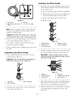
4. Remove the plastic ring nut on the existing outlet
drain and push the drain up into the tank. From
the inside of the machine remove the outlet drain
(Figure 46). Discard the valve outlet and locking nut.
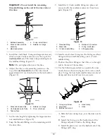
5. Locate the metal template in loose parts. Line up the
large hole in the template over the hole in the tank
(Figure 47).
G005875
1
2
Figure 47
1.
Sump, main tank
2.
Metal template
6. Mark the four smaller holes and drill four 6.4
mm (1/4 inch) diameter holes at the marked spot
(Figure 47).
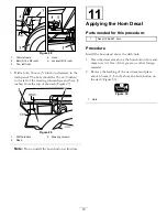
7. Locate the tank drain in loose parts. Disassemble the
drain if needed into the internal tank drain, rubber
seal and the external, lower section.
8. Drop the new drain base into the tank and move it
into position over the drain hole and new drilled
holes (Figure 48).
G005876
1
2
3
4
5
6
Figure 48
1.
Drain base
4.
Cover
2.
Drilled hole, 6.4 mm (1/4
inch)
5.
Lock washer (1/4 inch)
3.
Rubber seal
6.
Lock nut (1/4 inch)
9. Bring the threaded posts down through the drilled
holes. Install the rubber seals over the posts
(Figure 48).
10. Install the cover over the rubber seal and posts
(Figure 48). Secure the cover with four lock washers
(1/4 inch) and four lock nuts (1/4 inch).
11. Locate the 90 degree elbow fitting. Wrap Teflon tape
around the threads of the fitting.
12. Install the new elbow fitting to the drain (Figure 49).
Once fully installed, make sure the barb of the fitting
is pointing to the front, left side of the machine or
22


