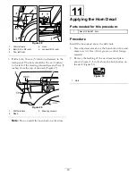
G005801
1
2
3
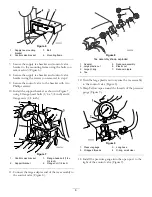
Figure 24
1.
Rinse nozzle valve decal,
part number 107-8785
3.
Flow of valve
2.
Rinse nozzle valve, green
3. Brush a non-petroleum based lubricate such
as vegetable oil on the bulkhead fitting reducer
(Figure 22).
4. Install the bulk reducer fitting to the rinse tank side
of the valve. Secure it with a large retainer fork from
loose parts.
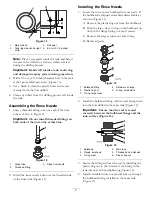
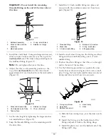
5. Install the rinse nozzle valve in the orientation
shown in Figure 25 for machines with a spray gun
attachments installed.
G005802
5
2
3
4
1
6
7
Figure 25
1.
Rinse tank valve, blue
5.
Boom supply hose,
existing
2.
Rinse nozzle valve, green
6.
Retainer fork, large
3.
Control valve, spray gun
7.
Retainer fork, large,
existing
4.
Rinse nozzle hose
6. Remove the retainer fork and the boom supply hose
from the spray gun control valve.
7. Install the rinse nozzle valve into the control valve
at the now open port. Orientate the flow of the
valve vertically so the rinse nozzle hose side of the
decal is on the top and the boom supply side is on
the bottom.
8. Use a existing, large retainer fork to secure the rinse
nozzle valve in the correct orientation.
9. Secure the boom supply hose to the boom supply
side of the rinse nozzle valve with the existing, large
retainer fork.
12

