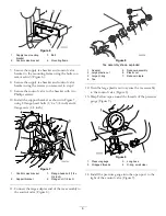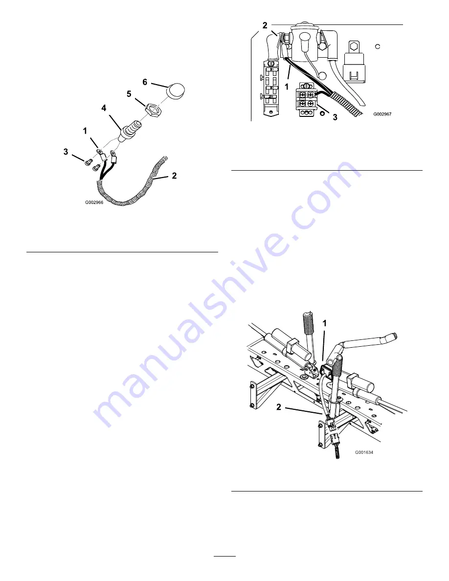
2. Remove the horn button cap and thread the retaining
ring onto the exposed threads of the switch.
3. Connect the white and yellow wires at the end of the
wire harness to the back of the horn switch using the
two screws included (Figure 37).
Figure 37
1.
White and red wires
4.
Horn switch
2.
Wire harness
5.
Retaining ring
3.
Screws
6.
Horn button
4. Move the switch assembly under the dash and push
it through the hole drilled in the dash previously.
5. Screw the horn button cap onto the switch threads
to secure the assembly to the dash.
Note:
Adjust the retaining ring and horn button
cap as necessary.
Installing the Wire Harness for Horn
and Brake
1. Run the wire harness from the horn button, under
the dash panel, through the wire access hole in the
floorboard, and through the frame hooks along side
of the headlight wire harness to the electrical panel
located under the operator’s seat.
2. Under the floorboard, connect the wire harness to
the new brake switch. Secure the harness to the
switch using a plastic wire tie.
3. Under the floor board, connect the two quick
connect terminals on the black and white wires to
the horn.
4. Under the operator’s seat, connect the single black
wire (ground) in the middle of the wire harness to
the ground block (Figure 38) located under the seat
near to the solenoid.
Note:
Right and left sides are determined from the
normal operating position.
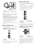
Figure 38
1.
Red power wire from the
wire harness.
3.
Black wire to ground block
2.
Solenoid, hot or input side
5. Connect the red power wire to the right side of the
solenoid (Figure 38), located under the seat.
Note:
Connecting the wire harness to the hot or
input side solenoid post will allow the horn to be
active when the ignition key is in the Off position.
Note:
The hot or input side has constant 12V
power.
6. Run the wire harness end with the tail light connector
along the left side of the frame toward the rear of
the machine.
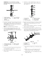
7. Connect the tail light connector on the wire harness
to the tail light (Figure 39).
Figure 39
1.
Tail light
2.
Pigtail connector
8. Tie the wire harness down to the frame along with
the existing wiring.
Note:
Make sure the harness does not touch any
part of the engine exhaust system.
18


