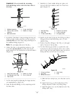
2. Plumb the hose from the bottom of the rinse tank to
the rinse tank valve so that the hose wraps around
the pump and is routed along the main pump hose.
3. Route the rinse tank suction hose behind the valve
assembly to the rinse tank side of the rinse tank valve.
Important:
Install the rinse tank suction hose
so that the check valve arrow shows the direction
of flow from the rinse tank to the rinse tank valve.
4. Secure the hose to the rinse tank using the small
retainer fork in loose parts.
5. Install the hose to the input side of the rinse tank
valve and secure it with the retainer fork included
in loose parts.
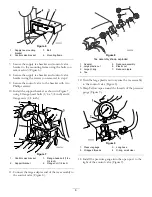
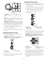
6. Use the plastic ties located in loose parts to secure
the rinse tank suction hose to the main pump hose
as shown in Figure 26.
Installing the Rinse Nozzle Hose
1. Locate rinse nozzle hose assembly set aside earlier.
2. Install the hose to the input side of the rinse nozzle
valve.
3. Plumb the hose under and behind the main pump
and main tank suction hose, to the barbed elbow
fitting in the rinse tube (Figure 26).
4. Secure the rinse nozzle hose to the 60 degree elbow
fitting by threading the small retainer nut over the
elbow fitting. Make sure the small, clear O-ring is
seated in the small retainer nut at the end of the rinse
nozzle hose. Hand tighten.
9
Installing the Battery Cover
Fasteners
Parts needed for this procedure:
2
Flange bolt (5/16 x 3/4 inch)
2
Flange nut (5/16 inch)
Procedure
Replace the battery cover hand knobs with fasteners
from the CE kit.
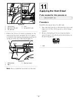
1. Loosen and remove the two hand knobs securing
battery cover to battery base (Figure 27).
Figure 27
1.
Hand knob
3.
Battery cover
2.
Battery
2. Install the two flange bolts (5/16 x 3/4 inch) and
two flange nuts (5/16 inch) in place of the removed
hand knob to secure the battery cover.
10
Installing the Horn
Parts needed for this procedure:
1
Horn
1
Bolt (5/16 x 3/4 inch)
1
Locknut (5/16 inch)
Procedure
Prepare the machine for the installation of the horn.
1. Drill a hole, 8.5 mm ( 11/32 inch) in diameter, in
the vehicle frame under the floorboard. The hole
should be 4 cm (1-1/2 inches) down from the frame
top and 5 cm (2 inches) from the front of the frame
(Figure 28).
2. Secure the horn to the frame using a bolt (5/16 x
3/4 inch) and a locknut (5/16 inch) as shown in
Figure 28.
14

