16
Installing Brake Switch
Parts needed for this procedure:
1
2
Bolt (3/16 x 5/8 inch)
2
Lock washer
2
Nut (3/16 inch)
Procedure
Install the brake switch to operate the tail light.
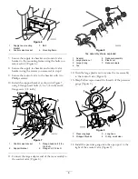
1. Install the brake switch to the brake lever using the 2
bolts (3/16 x 5/8 inch), lock washer, and nut (3/16
inch) as shown in Figure 40.
Figure 40
1.
Brake switch
4.
Lock washer
2.
Bolt (3/16 x 5/8 inch)
5.
Mount
3.
Nut (3/16 inch)
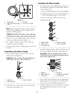
2. Adjust the new switch so the brake button is
depressed 6 mm (1/4 inch) when the brake is
released (Figure 41).
Figure 41
1.
New brake switch
3.
Brake released
2.
Brake engaged
Note:
If the brake light stays on when the pedal
released, loosen the bolts securing the brake switch
and adjust position of the switch so the light
extinguishes when the pedal is released.
17
Installing the Pressure Gauge
Parts needed for this procedure:
1
Pressure gauge
Procedure
Note:
Discard the pressure gauge that comes with the
CE kit. Use the pressure gauge located in the loose parts
of the BBA kit that displays only Bar.
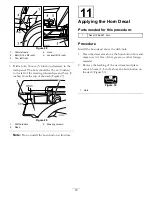
1. Using a wrench, hold the reducer at the tee bracket
and loosen the existing pressure gauge. Remove the
gauge (Figure 42).
Note:
The hole in the tee bracket should be slotted.
If not, use a drill to slightly elongate hole to allow
for the larger pressure gauge to fit.
19


