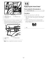
D. Install the barbed fitting assembly into the open
end of the rinse nozzle hose.
E. Tighten the hose clamp.
13. Set the rinse nozzle hose assembly aside for later
installation.
7
Installing the Valves
Parts needed for this procedure:
1
Decal, 107-8784, rinse tank valve
1
Decal, 107-8785, rinse nozzle valve
1
Rinse tank valve
1
Rinse nozzle valve
1
Reducer
4
Retainer fork, large
Installing the Rinse Tank Valve
1. Locate the blue rinse tank valve in loose parts and
the decal.
2. Install the decal number 107-8784 onto the valve
face in the correct orientation (Figure 21). Make sure
the decal aligns with the flow of the valve.
3
1
2
G005798
Figure 21
1.
Rinse tank valve decal,
part number 107-8784
3.
Flow of valve
2.
Rinse tank valve, blue
3. Disconnect the suction hose running from the top
of the main tank to the upper mixer tee. Discard this
hose and retain the forks for later use.
4. Brush a non-petroleum based lubricate such as
vegetable oil on the bulkhead fitting reducer and
O-ring (Figure 22)
1
2
G005799
Figure 22
1.
Brush
2.
Reducer
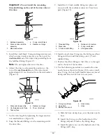
5. Install the bulk reducer fitting to the rinse tank
side of the valve (Figure 23). Secure it with a large
retainer fork from loose parts.
G005800
1
2
3
4
5
6
7
8
Figure 23
1.
Rinse tank valve, blue
5.
Upper mixer tee
2.
Reducer bulkhead fitting
6.
Retainer fork, large
3.
O-ring
7.
Apply non-petroleum
based lubricant here.
4.
Decal, 107–8784
8.
Retainer fork, existing
6. Install the tank rinse valve onto the top mixer tee
as shown in Figure 23 with the bulkhead facing
rearward. Secure the valve with an existing, large
retainer fork.
Install the Rinse Nozzle Valve
1. Locate green rinse nozzle valve in loose parts.
2. Install decal 107-8785 onto the valve face in the
correct orientation (Figure 24). Make sure the decal
aligns with the flow of the valve.
11

