


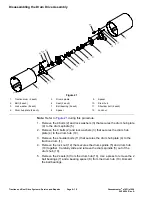
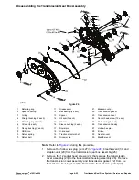
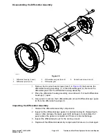
Disassembling the Transmission Gear Box Assembly (continued)
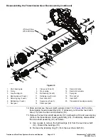
C. Slide and remove the slider spur gear (14) from the reel drive shaft (12).
D. Remove the two key squares (13) from the reel drive shaft (12).
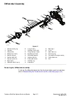
16. Remove the nut (8) and long bearing pin (3) that secures the spur gear
assembly (7) to the transmission housing assembly (20). Remove the spur
gear (7) and bearing spacer (4) from the transmission housing assembly (20).
17. Remove and discard the O-ring (2) from the long bearing pin (3).
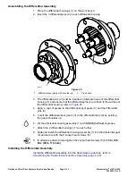
18. If necessary, disassemble the spur gear (7) as follows:
A. Remove the 2 retaining rings (5) from the spur gear (7).
B. Use a press and remove the 3 ball bearings (6) from the spur gear (7).
Discard the ball bearings.
19. Remove the nut (8) and short bearing pin (1) that secures the spur gear
assembly (17) to the transmission housing assembly (20). Remove the spur
gear (17) and bearing spacer (4) from the transmission housing assembly
(20).
20. Remove and discard the O-ring (2) from the short bearing pin (1).
21. If necessary, disassemble the spur gear (17) as follows:
A. Remove the 2 retaining rings (5) from the spur gear (17).
B. Use a press and remove the 2 ball bearings (6) from the spur gear (17).
Discard the ball bearings (6).
22. Remove the thin lock nut (18) that secures the input shaft (19) to the
transmission housing assembly (20). Slide and remove the input shaft.
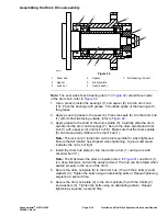
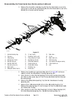
23. Remove the ORB plug (item 8 in
), detent spring (9) and detent ball
(10) from the transmission housing assembly (26).
24. Loosen and remove the groomer pin (item 20 in
) from the traction
selector shaft (19).
25. Remove the retaining ring (item 1 in
), spacer bushing (2) and
O-ring (3) from the traction selector shaft (19).
26. Slide and remove the traction selector shaft (item 19 in
) and O-ring
(18) from the transmission housing assembly (26).
27. Remove oil seal (item 15 in
) and sleeve bushings (16) from the
transmission housing (26). Discard the oil seal (15).
28. Remove the flange bushings (item 7 in
) from the transmission
housing (26).
29. Remove the oil seals (item 6 in
), grease seals (11) and retaining
ring (5) from the transmission housing (26). Discard the oil seals and grease
seals.
30. Use a press and remove the ball bearings (items 12 and 25 in
) and
spacer (13) from the transmission housing (26). Discard the ball bearings
(12 and 25).
Greensmaster
®
e1021/e1026
Page 4–27
Traction and Reel Drive Systems: Service and Repairs
20246SL Rev A
Содержание 04831
Страница 4: ...NOTES NOTES Page 4 Greensmaster e1021 e1026 20246SL Rev A ...
Страница 6: ...g340650 Figure 1 Model 04831 shown Preface Page 6 Greensmaster e1021 e1026 20246SL Rev A ...
Страница 14: ...Safety Safety and Instructional Decals Page 1 6 Greensmaster e1021 e1026 20246SL Rev A ...
Страница 46: ...Troubleshooting Battery Charger Error and Fault Codes Page 3 14 Greensmaster e1021 e1026 20246SL Rev A ...
Страница 136: ...Electrical System Service and Repairs Page 5 56 Greensmaster e1021 e1026 20246SL Rev A ...
Страница 162: ...Controls Wheels and Accessories Service and Repairs Page 6 26 Greensmaster e1021 e1026 20246SL Rev A ...
Страница 210: ...Universal Groomer Optional Service and Repairs Page 8 20 Greensmaster e1021 e1026 20246SL Rev A ...
Страница 213: ...Greensmaster e1021 e1026 Drawing 122 1647 Rev A Sheet 1 of 1 20246SL Rev A Page A 3 Electrical Schematic g361655 ...
Страница 214: ...Page A 4 20246SL Rev A Greensmaster e1021 e1026 Drawing 122 1734 Rev D Sheet 1 of 2 Wire Harness Drawing CV g361656 ...
Страница 215: ...Greensmaster e1021 e1026 Drawing 122 1734 Rev D Sheet 2 of 2 20246SL Rev A Page A 5 Wire Harness Drawing g361657 ...
Страница 216: ......


