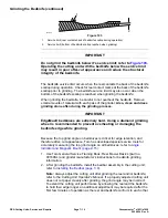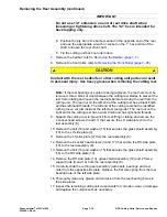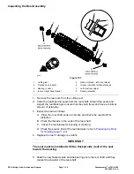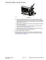
Installing the Reel Assembly (continued)
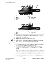
IMPORTANT
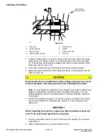
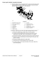
To avoid grinding the reel, do not contact the cutting edge of
any blade with the pry bar as this may damage the cutting edge
and/or cause a high blade.
B. Move the pry bar against the weld side of the reel support plate closest
to the bearing lock screw.
IMPORTANT
The reel drive shaft on the left end of the cutting reel has left hand
threads. The bearing lock screw on the right end of the cutting
reel has right- hand threads.
C. Rest the handle of the pry bar against the front roller and tighten the
bearing lock screw from
123 to 149 N·m (90 to 110 ft-lb)
.
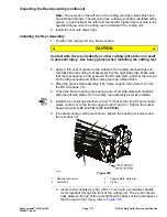
IMPORTANT
Do not use 1/2” extension on end of reel drive shaft when
loosening or tightening drive shaft. The 1/2” hex is intended for
back lapping only.
D. Position the pry bar in the same manner on the opposite end of the reel
and use the appropriate wrench or socket on the 1” hex portion of the
shaft to tighten the reel drive shaft from
123 to 149 N·m (90 to 110 ft-lb)
.
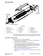
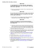
7. Secure the grass shield assembly (18) to the RH and LH side plates (4 and
10) with the 2 washers (15) and 2 bolts (16).
8. If the reel nuts were loosened during cutting reel service, put a block of wood
between the cutting reel blades to prevent the reel from rotating and tighten
the reel nuts from
123 to 149 N∙m (90 to 110 ft-lb)
.
9. Install the reel drive assembly; refer to
Installing the Reel Drive Assembly
(page 4–10)
. Grease the splines with high temp Mobil XHP−222 grease
or equivalent.
10. Install the bedbar assembly; refer to
Installing the Bedbar (page 7–8)
.
11. Install the front roller; refer to
Installing the Front Roller (page 7–27)
.
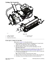
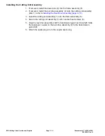
12. Install the cutting unit assembly to the frame assembly; refer to
Cutting Unit Assembly (page 7–16)
.
13. If the cutting unit is equipped with an optional groomer, install the components
for those options. Refer to
Removing the Gear Box Assembly (page 8–4)
for universal groomer, and
Universal Groomer (page 2–4)
for additional
information.
DPA Cutting Units: Service and Repairs
Page 7–22
Greensmaster
®
e1021/e1026
20246SL Rev A
Содержание 04831
Страница 4: ...NOTES NOTES Page 4 Greensmaster e1021 e1026 20246SL Rev A ...
Страница 6: ...g340650 Figure 1 Model 04831 shown Preface Page 6 Greensmaster e1021 e1026 20246SL Rev A ...
Страница 14: ...Safety Safety and Instructional Decals Page 1 6 Greensmaster e1021 e1026 20246SL Rev A ...
Страница 46: ...Troubleshooting Battery Charger Error and Fault Codes Page 3 14 Greensmaster e1021 e1026 20246SL Rev A ...
Страница 136: ...Electrical System Service and Repairs Page 5 56 Greensmaster e1021 e1026 20246SL Rev A ...
Страница 162: ...Controls Wheels and Accessories Service and Repairs Page 6 26 Greensmaster e1021 e1026 20246SL Rev A ...
Страница 210: ...Universal Groomer Optional Service and Repairs Page 8 20 Greensmaster e1021 e1026 20246SL Rev A ...
Страница 213: ...Greensmaster e1021 e1026 Drawing 122 1647 Rev A Sheet 1 of 1 20246SL Rev A Page A 3 Electrical Schematic g361655 ...
Страница 214: ...Page A 4 20246SL Rev A Greensmaster e1021 e1026 Drawing 122 1734 Rev D Sheet 1 of 2 Wire Harness Drawing CV g361656 ...
Страница 215: ...Greensmaster e1021 e1026 Drawing 122 1734 Rev D Sheet 2 of 2 20246SL Rev A Page A 5 Wire Harness Drawing g361657 ...
Страница 216: ......

