

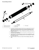


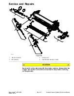

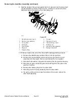


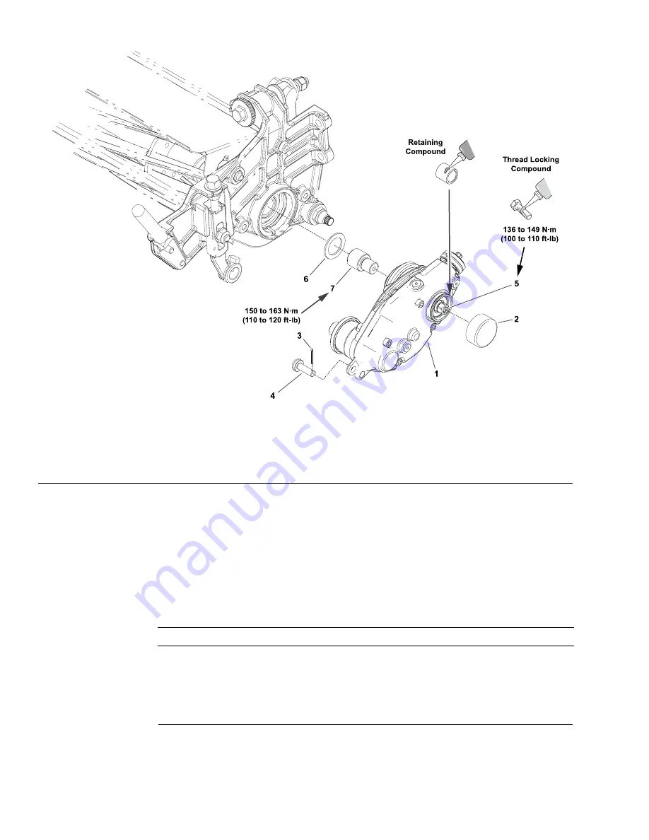
The Gear Box Assembly
g287374
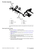
Figure 115
1.
Gear box assembly
4.
Clevis pin
7.
Adapter
2.
Drive shield
5.
Input shaft
3.
Cotter pin
6.
Shim
The groomer gear box assembly is located on the opposite side of the cutting
unit from the reel drive.
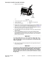
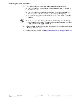
Removing the Gear Box Assembly
1. Remove the groomer reel assembly; refer to
(page 8–14)
.
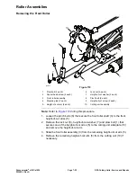
2. Safely prevent the reel from rotating by blocking the cutting reel with a piece
of wood near one of the reel spiders.
IMPORTANT
The groomer gear box for this machine is installed on the left side of
the cutting unit. Groomer gear boxes installed on the left side of the
cutting unit use a left hand thread. Turn the input shaft clockwise
to remove the gear box.
Universal Groomer (Optional): Service and Repairs
Page 8–4
Greensmaster
®
e1021/e1026
20246SL Rev A
Содержание 04831
Страница 4: ...NOTES NOTES Page 4 Greensmaster e1021 e1026 20246SL Rev A ...
Страница 6: ...g340650 Figure 1 Model 04831 shown Preface Page 6 Greensmaster e1021 e1026 20246SL Rev A ...
Страница 14: ...Safety Safety and Instructional Decals Page 1 6 Greensmaster e1021 e1026 20246SL Rev A ...
Страница 46: ...Troubleshooting Battery Charger Error and Fault Codes Page 3 14 Greensmaster e1021 e1026 20246SL Rev A ...
Страница 136: ...Electrical System Service and Repairs Page 5 56 Greensmaster e1021 e1026 20246SL Rev A ...
Страница 162: ...Controls Wheels and Accessories Service and Repairs Page 6 26 Greensmaster e1021 e1026 20246SL Rev A ...
Страница 210: ...Universal Groomer Optional Service and Repairs Page 8 20 Greensmaster e1021 e1026 20246SL Rev A ...
Страница 213: ...Greensmaster e1021 e1026 Drawing 122 1647 Rev A Sheet 1 of 1 20246SL Rev A Page A 3 Electrical Schematic g361655 ...
Страница 214: ...Page A 4 20246SL Rev A Greensmaster e1021 e1026 Drawing 122 1734 Rev D Sheet 1 of 2 Wire Harness Drawing CV g361656 ...
Страница 215: ...Greensmaster e1021 e1026 Drawing 122 1734 Rev D Sheet 2 of 2 20246SL Rev A Page A 5 Wire Harness Drawing g361657 ...
Страница 216: ......


