
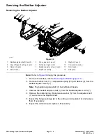


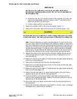


Removing the Reel Assembly (continued)
IMPORTANT
Do not use 1/2” extension on end of reel drive shaft when
loosening or tightening drive shaft. The 1/2” hex is intended for
back lapping only.
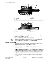
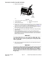
E. Position the pry bar in the same manner on the opposite end of the reel
and use the appropriate wrench or socket on the 1” hex portion of the
shaft to loosen the reel drive shaft.
F. Tip the cutting unit back onto its rollers.
7. Remove the bedbar; refer to
Removing the Bedbar (page 7–7)
.
8. Remove the front roller; refer to
Removing the Front Roller (page 7–25)
.
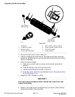
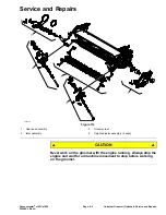
CAUTION
Contact with the reel, bedknife or other cutting unit parts can result
in personal injury. Use heavy gloves when removing the cutting reel.
Note:
If the reel bearings or seals are being replaced, the reel nuts must be
removed. Use a block of wood between the cutting reel blades to prevent the
reel from rotating and loosen the reel nuts before removing the reel from the
cutting unit. The reel nut on the left end of the cutting reel has a black finish
and has left-hand threads. The left end of the cutting reel shaft is identified
with a groove cut just inside of the left-most reel spider. The reel nut on the
right end of the cutting reel has a silver finish and has right-hand threads.
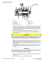
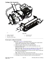
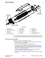
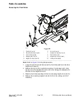
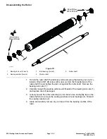
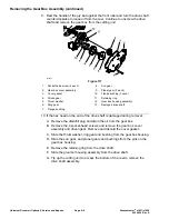
9. Support the cutting reel to prevent it from shifting or falling and remove the
2 socket head screws (3 and 17) that secure the LH side plate (4) to the
reel assembly (8).
10. Remove the bolt (16) and washer (15) that secures the grass shield assembly
(18) to the LH side plate (4).
11. Remove the LH side plate (4) from the reel assembly (8).
12. Remove the 2 socket head screws (3 and 17) that secure the RH side plate
(10) to the reel assembly (8).
13. Remove the bolt (16) and washer (15) that secures the grass shield assembly
(18) to the RH side plate (10).
14. Remove the RH side plate (10), grass shield assembly (18) and 2 frame
support rods (9 and 14) from the reel assembly (8).
15. Carefully slide the cutting reel assembly (with seals, bearings and reel
nuts) from the opposite side plate. Retrieve the flat wire spring from the reel
bearing bore of the left side plate.
16. Thoroughly clean any grease and corrosion from the reel bearing bores in
the side plates.
17. Inspect the remaining cutting unit components for corrosion, wear, or damage
and replace the components as necessary.
Greensmaster
®
e1021/e1026
Page 7–19
DPA Cutting Units: Service and Repairs
20246SL Rev A
Содержание 04831
Страница 4: ...NOTES NOTES Page 4 Greensmaster e1021 e1026 20246SL Rev A ...
Страница 6: ...g340650 Figure 1 Model 04831 shown Preface Page 6 Greensmaster e1021 e1026 20246SL Rev A ...
Страница 14: ...Safety Safety and Instructional Decals Page 1 6 Greensmaster e1021 e1026 20246SL Rev A ...
Страница 46: ...Troubleshooting Battery Charger Error and Fault Codes Page 3 14 Greensmaster e1021 e1026 20246SL Rev A ...
Страница 136: ...Electrical System Service and Repairs Page 5 56 Greensmaster e1021 e1026 20246SL Rev A ...
Страница 162: ...Controls Wheels and Accessories Service and Repairs Page 6 26 Greensmaster e1021 e1026 20246SL Rev A ...
Страница 210: ...Universal Groomer Optional Service and Repairs Page 8 20 Greensmaster e1021 e1026 20246SL Rev A ...
Страница 213: ...Greensmaster e1021 e1026 Drawing 122 1647 Rev A Sheet 1 of 1 20246SL Rev A Page A 3 Electrical Schematic g361655 ...
Страница 214: ...Page A 4 20246SL Rev A Greensmaster e1021 e1026 Drawing 122 1734 Rev D Sheet 1 of 2 Wire Harness Drawing CV g361656 ...
Страница 215: ...Greensmaster e1021 e1026 Drawing 122 1734 Rev D Sheet 2 of 2 20246SL Rev A Page A 5 Wire Harness Drawing g361657 ...
Страница 216: ......


