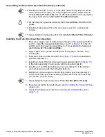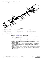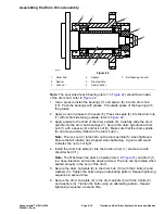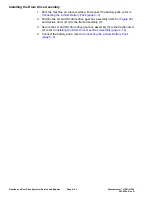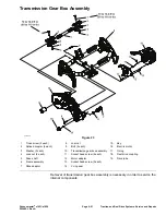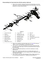
Assembling the Transmission Gear Box Assembly (continued)
19. Apply a coat of grease to the O-ring (item 2 in
) and slide the O-ring
onto the long bearing pin (3). Install the spur gear assembly (7) and bearing
spacer (4) onto the transmission housing assembly (20) and secure with
the long bearing pin (3) and nut (8).
20. Insert the square keys (item 13 in
) into the reel drive shaft (12) and
apply a coat of grease to outside of the keys.
21. Slide the slider spur gear (item 14 in
) onto the reel drive shaft
(12) and secure with the retaining rings (11). Press the new ball bearings
(10) onto the reel drive shaft (12).
22. Install the wave spring (item 9 in
) and reel drive assembly (14) into
the transmission housing assembly (20).
23. Insert the reel clutch shoe (item 15 in
) into the reel clutch actuator
(16). Slide the reel clutch actuator (16) into the transmission housing
assembly (20).
24. Assemble the brake lever assembly (item 19 in
) as follows:
A. Apply a coat of grease to the O-ring (item 20 in
) and slide the
O-ring onto the brake lever.
B. Place the brake lever (item 19 in
) onto the brake band (18) and
secure with the brake clevis pin (21) and retaining ring (17).
25. Slide and install the brake lever assembly (item 19 in
) into the
transmission housing assembly (23).
26. If removed, insert the brake mount pin through brake band into the
transmission housing assembly (item 23 in
), place the flat wire
spring (22) and brake plate retainer (16) onto the transmission housing
assembly.
27. Place the retainer plate pin (item 15 in
) onto the transmission
housing assembly (23) and secure it with the 2 bolts (8).
28. Slide and install the external retaining ring (item 1 in
), cable brake
lever (24) onto the brake lever (19) and secure it with the bolt (25).
29. If disassembled, assemble the differential assembly (item 14 in
refer to
Assembling the Differential Assembly (page 4–34)
.
30. Pack the differential assembly (item 14 in
) with grease and use
a press to install the 2 ball bearing (13) and 2 flange bearings (12) into the
differential assembly.
31. Apply a coat of grease to the 2 O-rings (item 10 in
) and slide the
O-rings to the differential shafts (9). Install the retaining rings (11) onto the
differential shaft (9).
32. Insert the 2 differential shafts (item 9 in
) into the differential housing
(14).
33. Insert the differential housing assembly (item 14 in
) into the
transmission housing assembly (23).
34. Insert the square keys (item 7 in
) into the neutral slider shaft (6).
Apply a coat of grease to outer surface of the square keys (7).
35. Insert the neutral slider shaft (item 6 in
) into the neutral spur gear
(5).
36. Use a press and insert the bearings (item 4 in
) onto the neutral
slider shaft (6).
Greensmaster
®
e1021/e1026
Page 4–29
Traction and Reel Drive Systems: Service and Repairs
20246SL Rev A
Содержание 04831
Страница 4: ...NOTES NOTES Page 4 Greensmaster e1021 e1026 20246SL Rev A ...
Страница 6: ...g340650 Figure 1 Model 04831 shown Preface Page 6 Greensmaster e1021 e1026 20246SL Rev A ...
Страница 14: ...Safety Safety and Instructional Decals Page 1 6 Greensmaster e1021 e1026 20246SL Rev A ...
Страница 46: ...Troubleshooting Battery Charger Error and Fault Codes Page 3 14 Greensmaster e1021 e1026 20246SL Rev A ...
Страница 136: ...Electrical System Service and Repairs Page 5 56 Greensmaster e1021 e1026 20246SL Rev A ...
Страница 162: ...Controls Wheels and Accessories Service and Repairs Page 6 26 Greensmaster e1021 e1026 20246SL Rev A ...
Страница 210: ...Universal Groomer Optional Service and Repairs Page 8 20 Greensmaster e1021 e1026 20246SL Rev A ...
Страница 213: ...Greensmaster e1021 e1026 Drawing 122 1647 Rev A Sheet 1 of 1 20246SL Rev A Page A 3 Electrical Schematic g361655 ...
Страница 214: ...Page A 4 20246SL Rev A Greensmaster e1021 e1026 Drawing 122 1734 Rev D Sheet 1 of 2 Wire Harness Drawing CV g361656 ...
Страница 215: ...Greensmaster e1021 e1026 Drawing 122 1734 Rev D Sheet 2 of 2 20246SL Rev A Page A 5 Wire Harness Drawing g361657 ...
Страница 216: ......


