Testing the Main Contactor (continued)
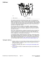
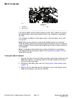
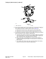
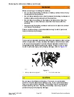
g339028
Figure 63
1.
Main contactor
3.
Coil post
2.
Main contact post
6. Use a multimeter to measure the voltage across the main contactor posts as
follows:
A. Position the rubber boots away from the main contactor posts to get
access to the posts with multimeter probes (
).
B. Connect the multimeter common (-) test probe to the ground connector in
the work light connector (step
).
C. Ensure that the traction lever is in the NEUTRAL position. Temporarily
connect the battery pack; refer to
Connecting the Lithium Battery Pack
(page 5–3)
.
D. Turn the key switch to the START position to wake up the machine and
then turn the key switch to the RUN position. The main contactor should
click as it is energized.
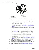
E. Use the second multimeter test probe, check that all 4 posts on the main
contactor have system voltage (42 V to 64 V @ 100% state of charge)
present (
). If 1 or more posts do not have system voltage
present, the contactor is damaged. If none of the posts have voltage
present, ensure that common (-) test probe is still connected to the work
light connector and if so, look for electrical issues at other machine
components as the contactor is not being energized correctly.
F. Turn the key switch to the OFF position. The main contactor should click
as it is de-energized.
G. Disconnect the battery pack; refer to
Connecting the Lithium Battery Pack
(page 5–3)
.
7. If testing determines that the main contactor is damaged, ensure that the
battery pack is disconnected and then replace the main contactor.
8. After you complete the main contactor testing, install the battery cover onto
the battery mount. Secure the battery cover with four bolts.
9. Connect the battery pack; refer to
Connecting the Lithium Battery Pack
(page 5–3)
.
Electrical System: Testing the Electrical Components
Page 5–38
Greensmaster
®
e1021/e1026
20246SL Rev A
Содержание 04831
Страница 4: ...NOTES NOTES Page 4 Greensmaster e1021 e1026 20246SL Rev A ...
Страница 6: ...g340650 Figure 1 Model 04831 shown Preface Page 6 Greensmaster e1021 e1026 20246SL Rev A ...
Страница 14: ...Safety Safety and Instructional Decals Page 1 6 Greensmaster e1021 e1026 20246SL Rev A ...
Страница 46: ...Troubleshooting Battery Charger Error and Fault Codes Page 3 14 Greensmaster e1021 e1026 20246SL Rev A ...
Страница 136: ...Electrical System Service and Repairs Page 5 56 Greensmaster e1021 e1026 20246SL Rev A ...
Страница 162: ...Controls Wheels and Accessories Service and Repairs Page 6 26 Greensmaster e1021 e1026 20246SL Rev A ...
Страница 210: ...Universal Groomer Optional Service and Repairs Page 8 20 Greensmaster e1021 e1026 20246SL Rev A ...
Страница 213: ...Greensmaster e1021 e1026 Drawing 122 1647 Rev A Sheet 1 of 1 20246SL Rev A Page A 3 Electrical Schematic g361655 ...
Страница 214: ...Page A 4 20246SL Rev A Greensmaster e1021 e1026 Drawing 122 1734 Rev D Sheet 1 of 2 Wire Harness Drawing CV g361656 ...
Страница 215: ...Greensmaster e1021 e1026 Drawing 122 1734 Rev D Sheet 2 of 2 20246SL Rev A Page A 5 Wire Harness Drawing g361657 ...
Страница 216: ......

