


Testing the Electrical Components
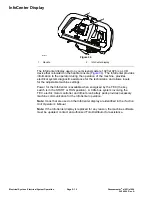
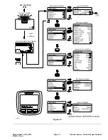
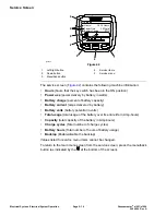
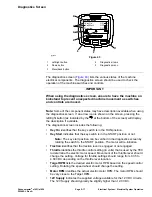
Whenever possible, check the component circuit operation with the InfoCenter
display on the console. With the key switch in the RUN position, use the
InfoCenter diagnostics menu to ensure that the component state changes as
the component is toggled. This quick check identifies that the component and
circuit wiring are working as designed. If the InfoCenter operation suggests
that a component circuit is not functioning correctly, proceed to the appropriate
component testing procedure found in this section. If the test procedure
identifies no problem with the component, carefully inspect the wire harness
and connectors for problems.
The Greensmaster uses a 48 VDC electrical system that is an isolated circuit.
The machine frame is not used for any ground connections.
For accurate resistance and/or continuity checks, electrically disconnect the
component being tested from the circuit (e.g., unplug the key switch connector
before doing a continuity check on switch). Individual components should be
electrically isolated (e.g., disconnect all the leads or remove the leads from the
circuit) from the circuit when tested.
CAUTION
When testing a machine electrical component for continuity
with a multimeter (ohms setting), ensure that the component is
disconnected from the machine wire harness to prevent current flow
through the component.
CAUTION
Remove all the jewelry, especially rings and watches, before doing
any electrical troubleshooting or testing. Disconnect the lithium
battery pack to open the battery circuit before working on the
electrical system.
Greensmaster
®
e1021/e1026
Page 5–21
Electrical System: Testing the Electrical Components
20246SL Rev A
Содержание 04831
Страница 4: ...NOTES NOTES Page 4 Greensmaster e1021 e1026 20246SL Rev A ...
Страница 6: ...g340650 Figure 1 Model 04831 shown Preface Page 6 Greensmaster e1021 e1026 20246SL Rev A ...
Страница 14: ...Safety Safety and Instructional Decals Page 1 6 Greensmaster e1021 e1026 20246SL Rev A ...
Страница 46: ...Troubleshooting Battery Charger Error and Fault Codes Page 3 14 Greensmaster e1021 e1026 20246SL Rev A ...
Страница 136: ...Electrical System Service and Repairs Page 5 56 Greensmaster e1021 e1026 20246SL Rev A ...
Страница 162: ...Controls Wheels and Accessories Service and Repairs Page 6 26 Greensmaster e1021 e1026 20246SL Rev A ...
Страница 210: ...Universal Groomer Optional Service and Repairs Page 8 20 Greensmaster e1021 e1026 20246SL Rev A ...
Страница 213: ...Greensmaster e1021 e1026 Drawing 122 1647 Rev A Sheet 1 of 1 20246SL Rev A Page A 3 Electrical Schematic g361655 ...
Страница 214: ...Page A 4 20246SL Rev A Greensmaster e1021 e1026 Drawing 122 1734 Rev D Sheet 1 of 2 Wire Harness Drawing CV g361656 ...
Страница 215: ...Greensmaster e1021 e1026 Drawing 122 1734 Rev D Sheet 2 of 2 20246SL Rev A Page A 5 Wire Harness Drawing g361657 ...
Страница 216: ......


